Building
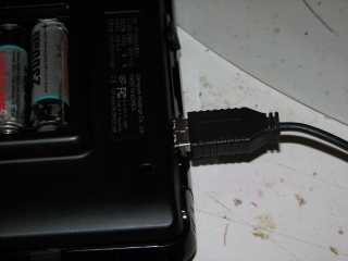
First of all, we need the USB data lines. These are on pins 9 and 10 of the
ext-port.
Cause we don't use an external port-connector, we'll have to solder the USB data wires to
the soldering side of the ext-connector. That's not easy: the pins have a real
small spacing, and soldering a wire to it means having a really steady hand and
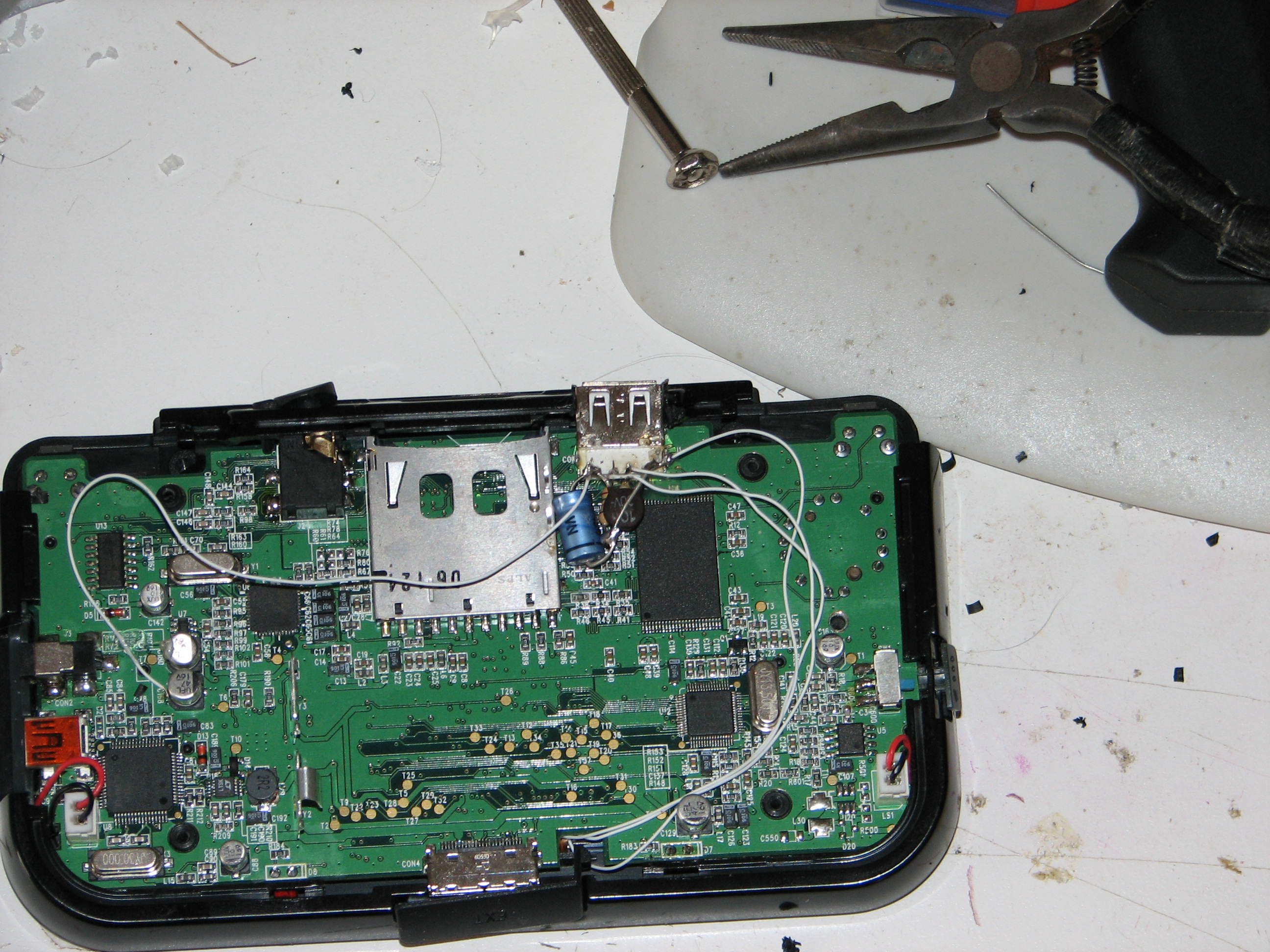
not having drunk any coffee in the last month. There are 2 vias on the other side
of the board that are a tad easier to solder to, though. See the pic if you want
to know where, or use a multimeter if the pic's not clear enough. (Btw: All pics
in this doc are viewable in full-size by clicking on them)
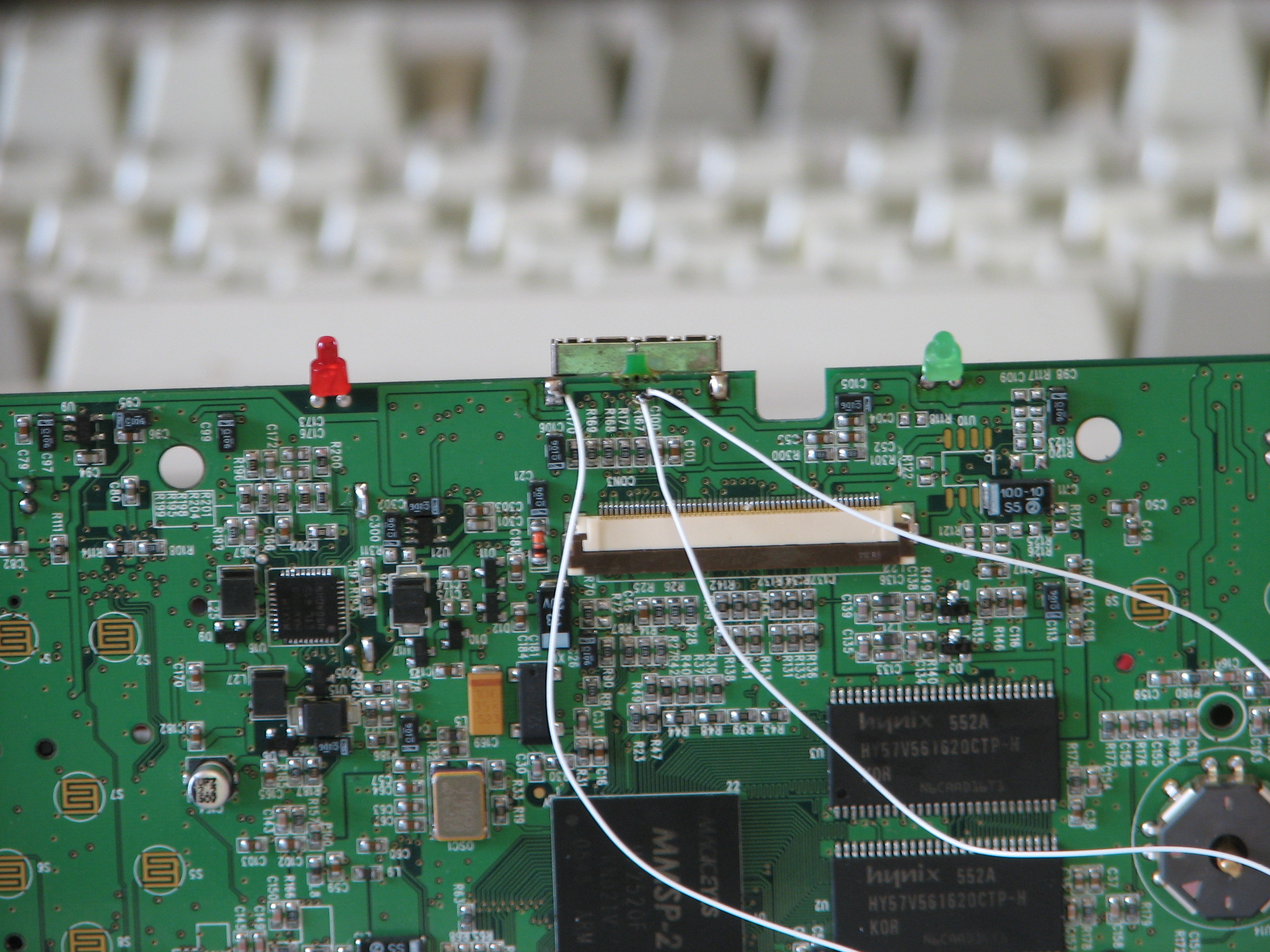
The via most to the center of the connector is USBH+, the other one is USBH-.
You'll need to scrape off the green varnish of the two vias first, then put some
solder on them. When you solder the wires to the vias, make sure the solder doesn't
come into contact with the ground trace next to them; use a multimeter if you're
not sure.
As you can see, I used this opportunity to solder a wire to the GP2Xs ground too.
If you're sure the wires are connected correctly, use a drop of hot glue to secure them:
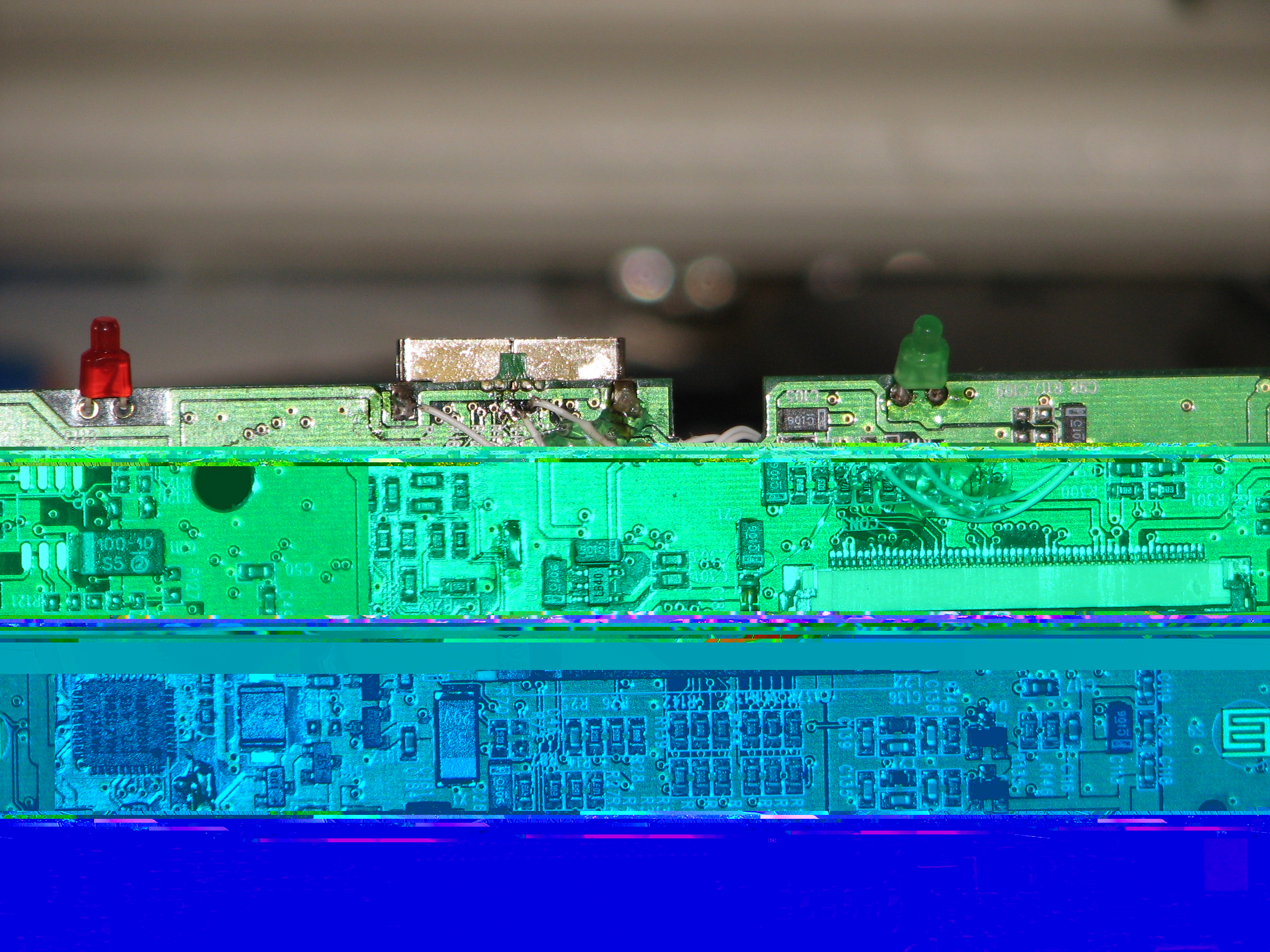
Next, we'll need the 5V for the USB power. This can be tapped the easiest from
the positive side of C158:

Again, use a drop of hot glue to fix the wire in place after you've made sure it doesn't
come into contact with any neighbouring traces.
Now that we've got the 4 wires, we can build the schematic around the USB-port.
This is what we're going to make:

(Sorry for the bad drawing, I'm running from a Knoppix cd cause my main HD crashed so I don't have access to my usual programs)
This scheme has been incorrect: the 15K resistors were wired wrongly. The scheme
you see now should be the correct one, with the 2 15K resistors pulling down the
data lines to ground. Thanks to the people who mailed me on this.
I've soldered these components directly to the USB-port, so I've hacked that in
place first: Use your favorite knife or rotating grinding tool/multitool/Dremel/...
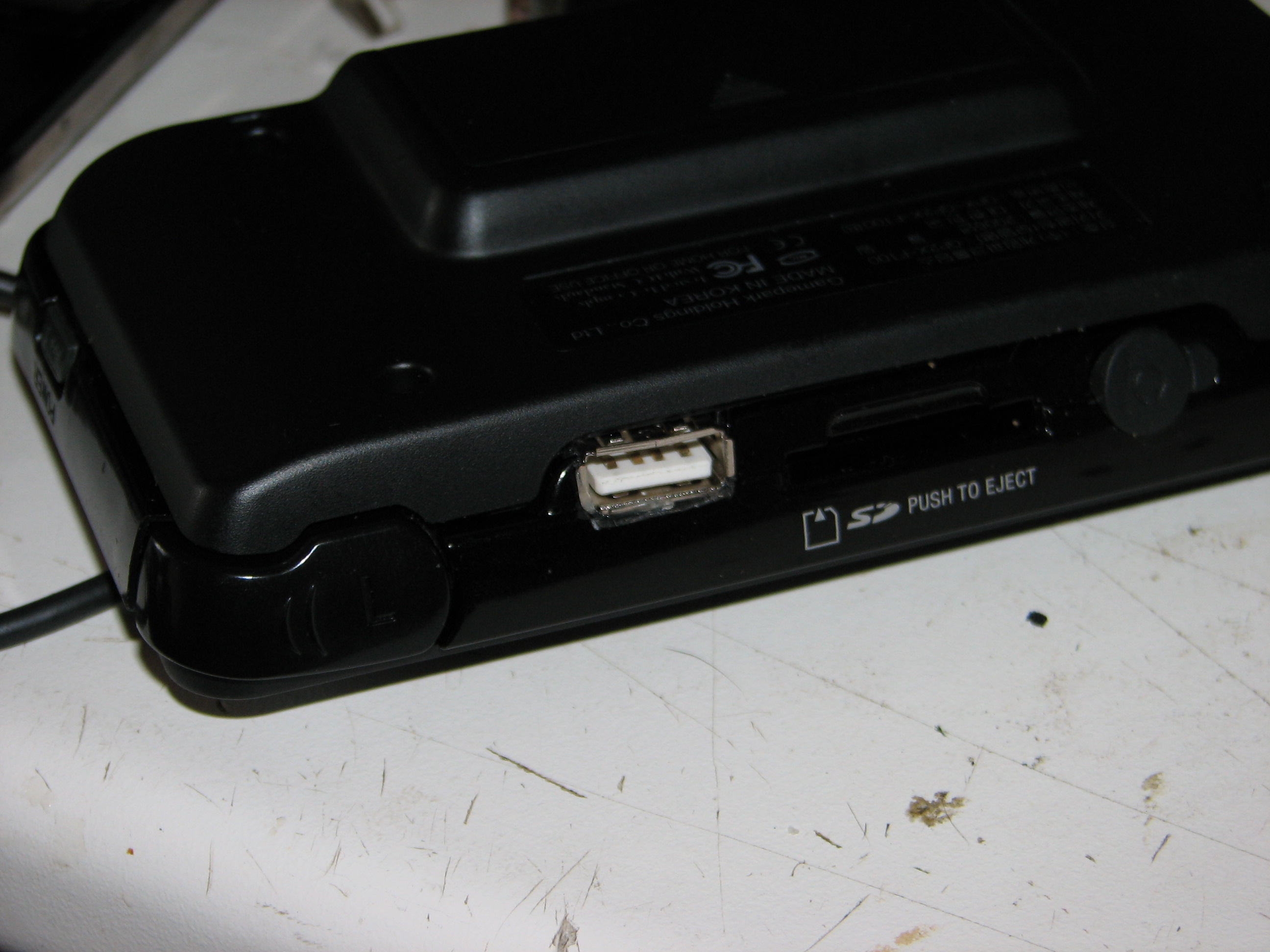
to create a hole in the GP2Xes casing, so the USB-connector can 'look outside'.
Then build the schematic so the wires of the components don't touch any metal
on the PCB of the GP2X when the connector is in place. Finally, fix the USB-port
in place with a drop of hot glue. Unfortunately, I don't have any pics of the
process, but finished it looks like this:

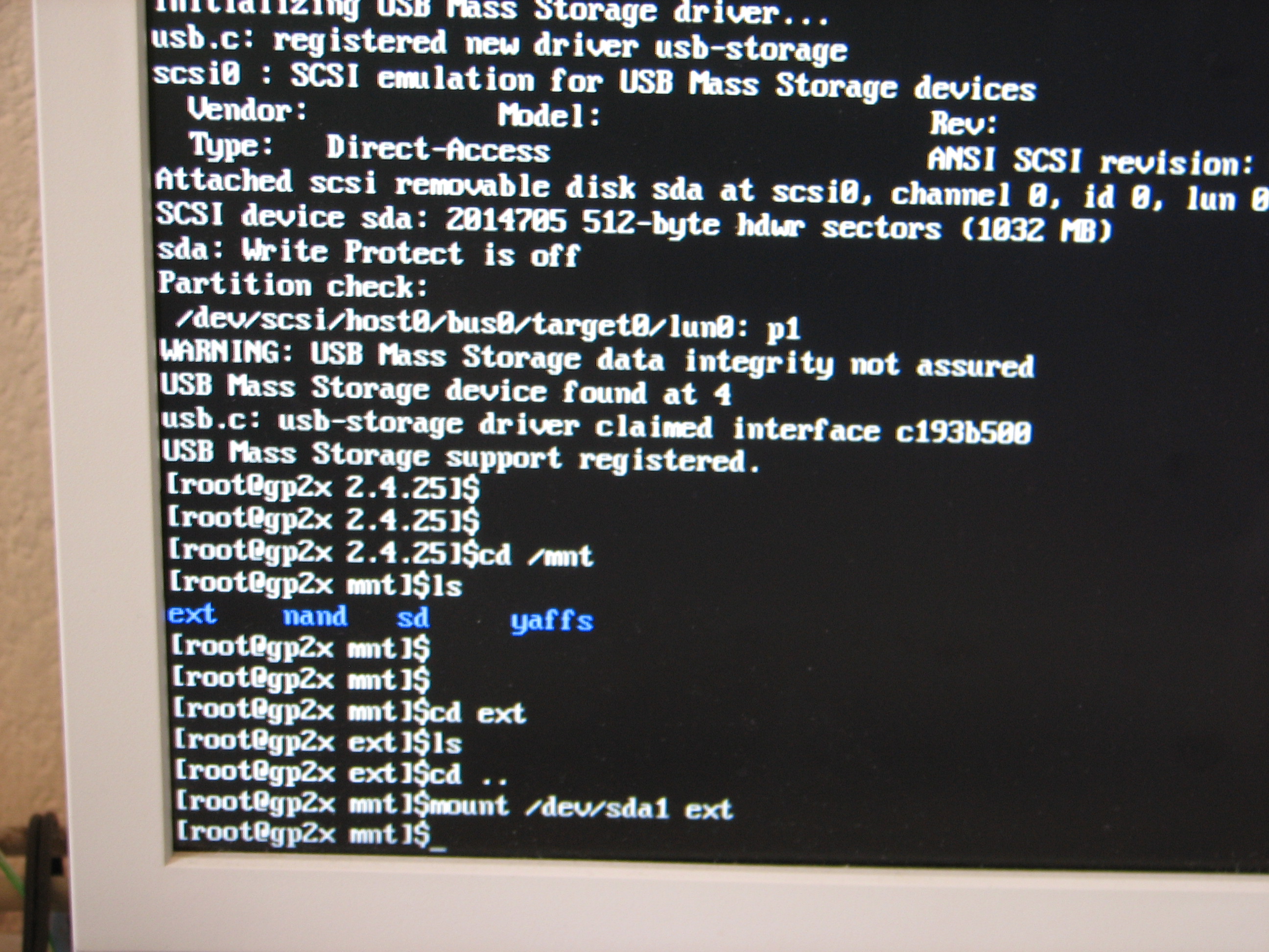
Next, let's see if it works. I used the usb-network-capabilities of the gp2x
to get a telnet console, and after some fiddling around with modules, I got this:
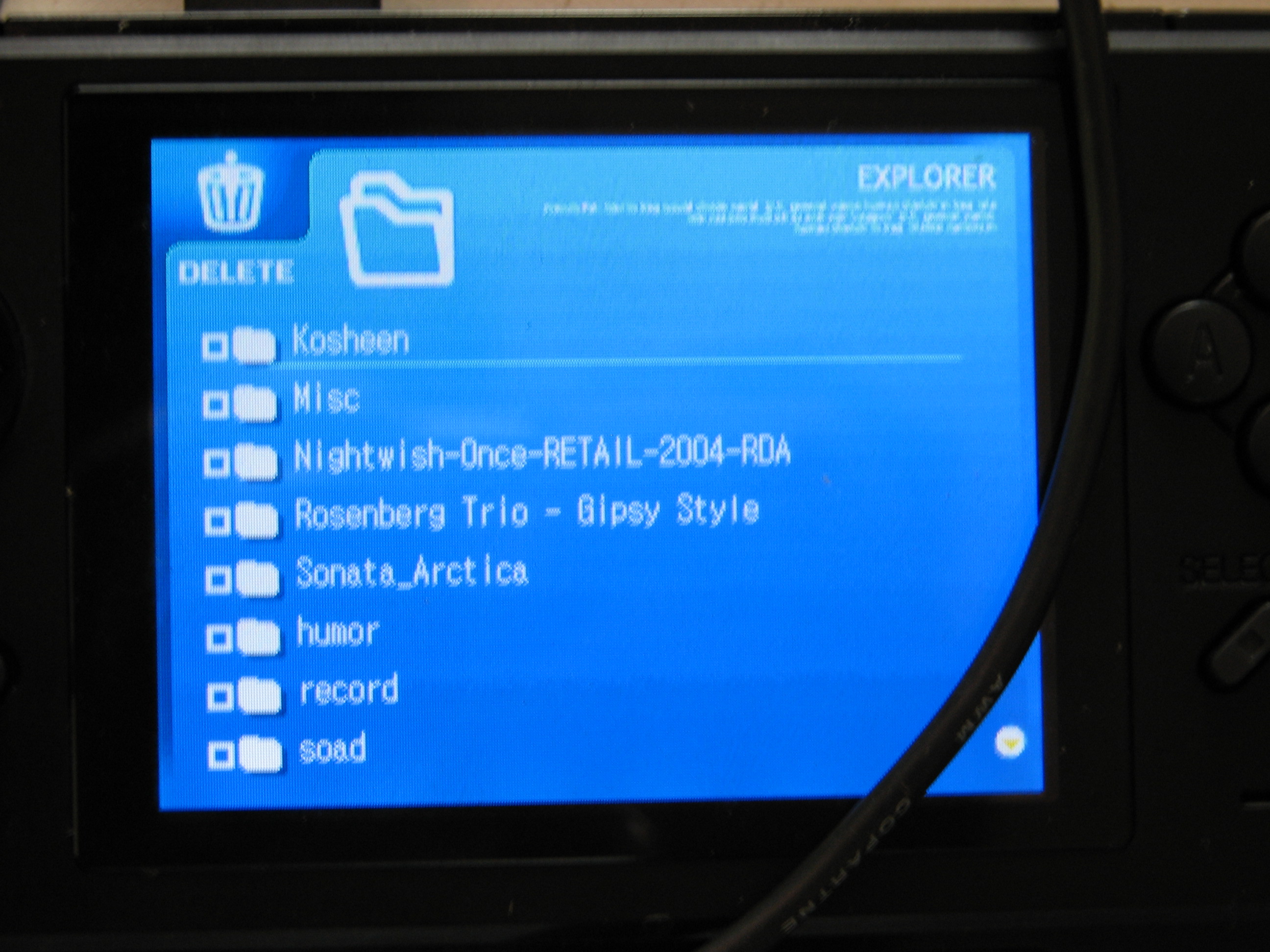
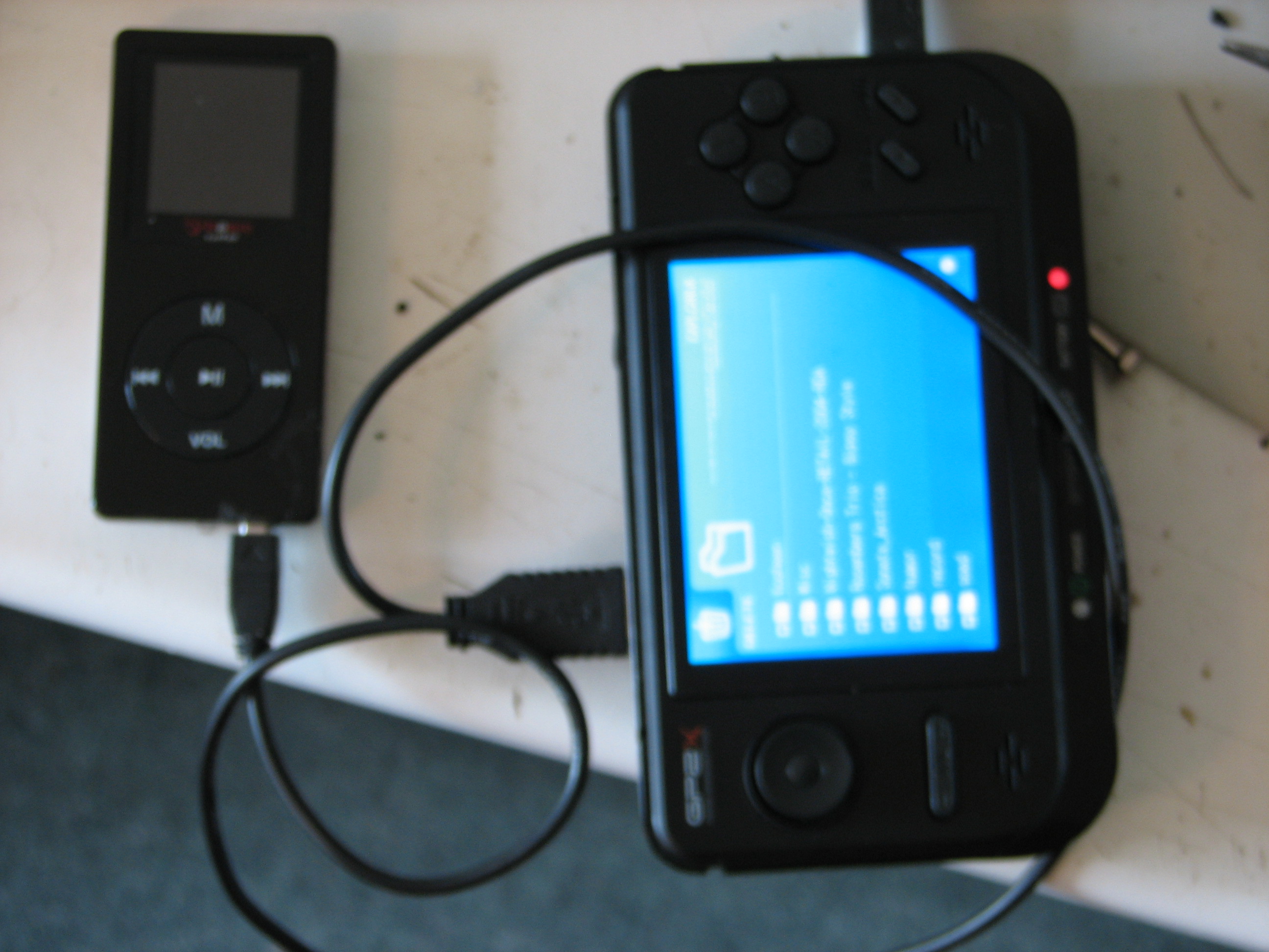
After screwing on the back of the GP2X, this is the result. Looks quite nicely,
although I managed to let the USB-connector get a tad crooked in the process.
No problem, it still fits OK.