Timing-attack
One of the 'standard' ways to tease information out of a badly-designed password-protected system is the timing attack. This type of attack is possible when the microcontroller does a simple string compare between the password and what's entered. In laymens terms: when the password is '12345' and what's entered is '23456', the microcontroller can immediately see that the password is wrong. If the password is '12345' and what's entered is '123888', the microcontroller first compares the 1, 2 and 3, and only when it arrives at the 4th digit it can see the password is wrong and bail out. The effect can be measurable: when a part of the password is OK, the microcontroller will take a tiny bit longer to report to the user that the password is wrong. That information can be used in order to get to the password much quicker than with bruteforcing it.
First it would be nice to find out the scale of things we have to measure. The difference in reaction time between entering a good and a wrong digit can be in the order of a few processor cycles, so finding out how long a processor cycle takes is fairly important. Now, how do we get that information? If the PIC derived its clock from an external crystal, it would be easy: just read the speed off the crystal. This PIC generates its clock speed internally, so we need to be more tricky.
Some background on how microcontrollers work: Like with all synchronous logic, everything in the PIC works in lockstep with the clock signal. When the clock starts a cycle, an instruction gets read in, a calculation gets done, data gets written etc. Because all of this is initiated at the start of the cycle, it's then when a microcontroller uses most of it's power: during the rest of the cycle the power usage is a bit less. In other words: by measuring the power supply, you should be able to read the clock frequency.
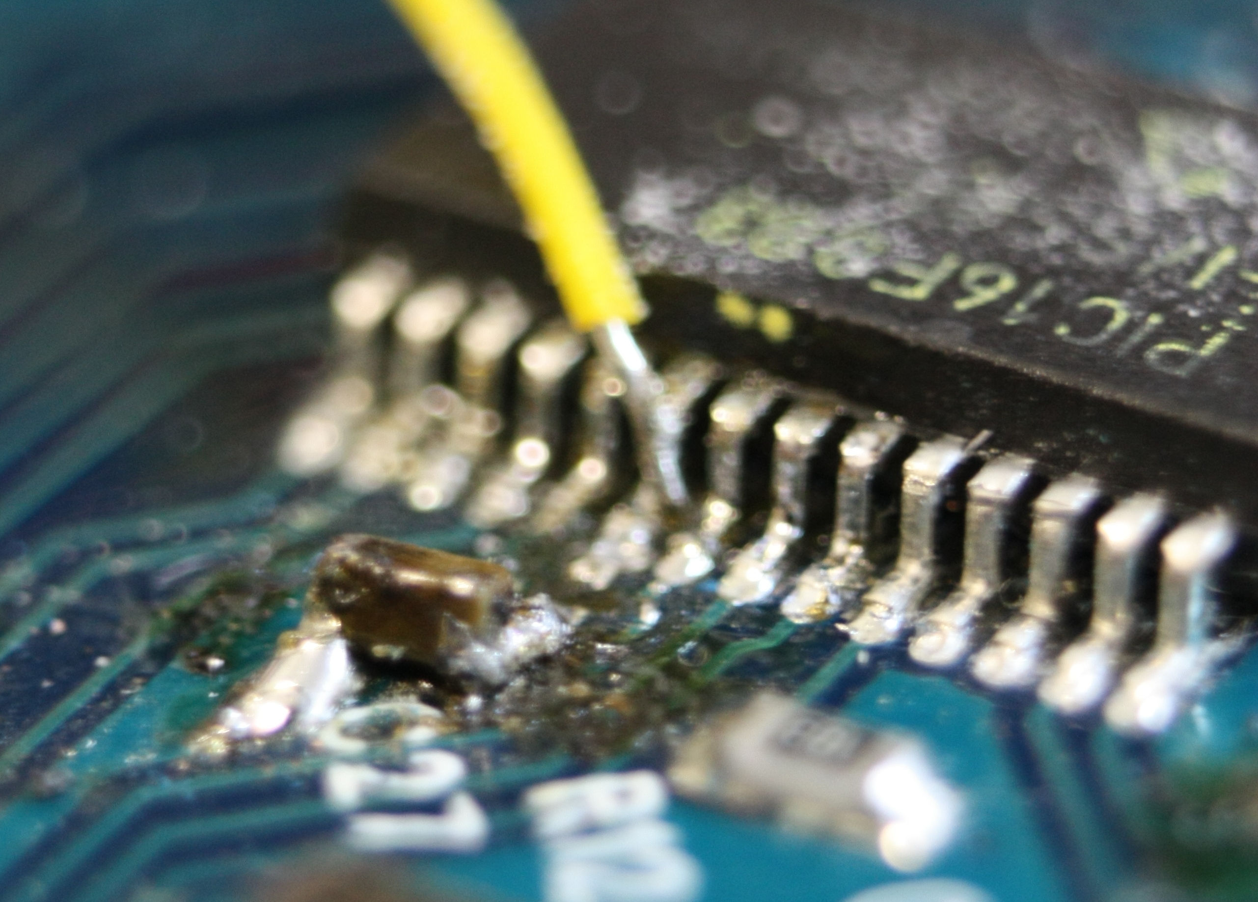
The way I did it was to cut the power line to the microcontroller and insert a 330 ohm resistor between it and the power supply. Then I connected an oscilloscope to the resistor and measured the waveform I saw. It turned out to be 8MHz, which corresponds to one of the frequencies the chip can use.
On to the timing-attack itself: I had to measure the time between when the password compare routine started to do its work and when it decided the password is wrong. The most obvious way to measure that was to measure the time between me pressing the button and the LED starting to blink to indicate an error. That would mean measuring a time difference of about a ten-millionth of a second on a timespan of about half a second: fairly impossible, given that over such a timespan the error in the clock signal can get quite big.
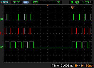
There were two other signals I could use, though. For the start-signal, I took a look at the keyboard-matrix. The keyboard-matrix is read out sequencially: first the first row is scanned for keypresses, then the second row, then the third row, then it all restarts at the first row etcetera. A more comprehensive explanation can be found somewhere else, for now it suffices to say that the 'selection' of keyboard rows is visible as three lines all pulsing regularily.
What happens when the unlock-key is pressed seemingly is so tasking for the little CPU that it'll stop the matrix scanning the moment it gets busy calculating if the pincode is correct or wrong. Seemingly, that process takes only 25mS, in which a timing difference of a cycles still is hard to measure but a bit more easy. Unfortunately, when I tried to measure the time taken, there still was a quite large random factor between two identical tries. Something was introducing jitter into the process, but what?
After some thought I recalled that the PIC 'remembers' the amount of wrong passwords entered even when you remove and re-apply power. That data has to be written into some kind of non-volatile memory; the PICs EEPROM is a good candidate for that. Writing the EEPROM is a tedious business: the chip needs to power up some on-die high power generators to generate the voltage to erase the EEPROM cells and then has to wait a certain amount of time before everything is written. That time is decided by some kind of analog timing circuit; could that be the culprit?
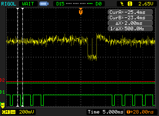
Ok, so now I had to see if I could spot the writing of the EEPROM somewhere. Luckily, the hardware already was there: the HV-generators that are turned on when the EEPROM gets written eat up a lot more power than the microcontroller itself does. With the resistor used for measuring the clock speed still in place, that meant a nice measurable dip in the power supply line to the chip.
Did that help? Unfortunately, no: the jitter in the measurements still was too big to see the few cycles difference expected here: between two entries of exactly the same pincode a difference in timing of more that 100 cycles was measured. While it's not possible to say if this is due to a random coincidence in the code or an explicit protection against this sort of timing-attack, fact remains that I couldn't get too much info this way. It did open up a few more possibilities to attack the device, though.