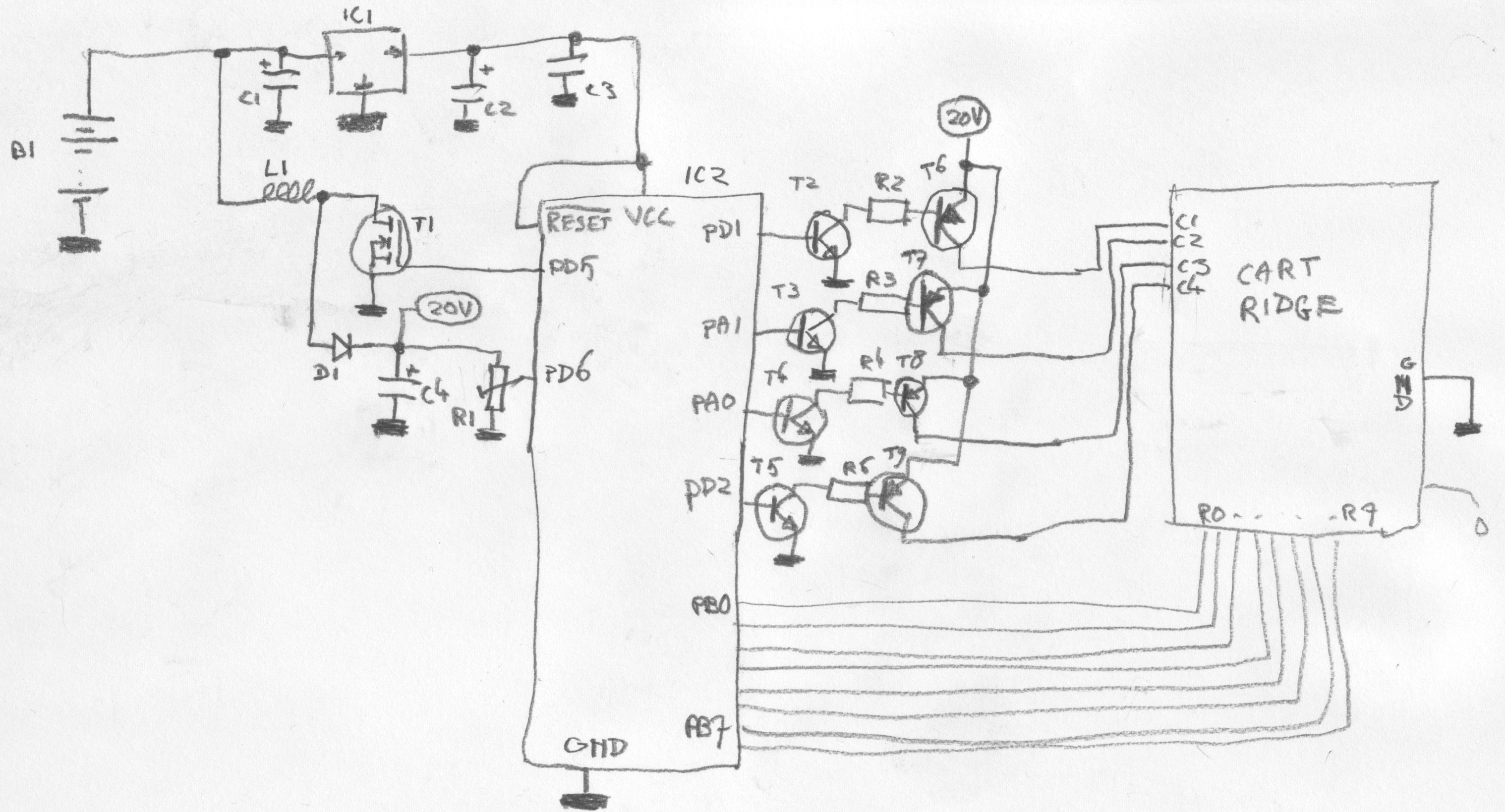
Schematic
The remainder of the circuit consists of nothing more than a microcontroller
(ATTiny2313), some electronics to ensure smooth communication with the
cartridge, a DC/DC converter to generate the required 20V for the nozzles,
a 78L05 for the power supply for the microcontroller and a 9-V battery as a
power supply.

(As always, click to enlarge)
Parts:
- B1: 9V battery
- C1, C2: electrolithic capacitor, 22uF
- C3: capacitor, 100nF
- C4: capacitor, 22uF, 25V
- L1: See text
- IC1: 78L05
- IC2: ATTiny2313
- D1: 1N4001
- R1: trimpotmeter, 10K
- R2-R5: 4K7
- T1: STD12NF06, see text
- T2-T5: BC550
- T6-T9: BC560
The DC/DC-converter consists of L1, D1, T1, C4, R1 and the PWM hardware of the microcontroller. These parts together form a simple 'boost' converter. This works as follows. The microcontroller attempts to keep the voltage at PD6 at 2.5 V. It does this by making the pulses it generates on PD5 longer or shorter. These pulses cause T1 to conduct which results in a current through L1. When T1 blocks, that current continues to flow for a short time due to L1. C4 is now charged via D1. The current that flows into C4 allows the voltage across C4 to be higher than the power supply voltage. This voltage is divided via R1 and supplied to PD6. In this way the microcontroller regulates the voltage across C4 to a set value. R1 is used to adjust the voltage across C4 to the required 20 V. Start with the potentiometer in the centre position and turn towards the ground connection to increase the voltage to 20 V. The power supply for the microcontroller is handled by the 78L05 and the necessary decoupling capacitors around it.
In addition to the PWM logic that is programmed into the microcontroller, there is also a simple character generator built in. Even though it is possible to obtain quite a high resolution (32 nozzles are being controlled) the font uses just 8x8 pixels per character. This low resolution was deliberate because there is only 2 k of flash ROM available in the microcontroller. By selecting a microcontroller with more ROM a better font could be used. A considerable amount of rummaging through the junkbox was involved for this project and unfortunately the author did not have a 'bigger' microcontroller on hand.
The characters are generated based on a small sentence in the flash ROM. These are then sent to the nozzles. The sectors are made active one by one and when a sector is active only one nozzle is activated. The reason that this is done for each individual nozzle is that the print head would otherwise create a local vacuum for itself. This would result in (temporarily) no ink from the print head. By changing the nozzles, the nozzles that are not driven are given time to fill with ink again.
The sector lines of the cartridge (C1 to C4) have to be powered with a voltage of 20 V to make a sector active. We do this with T2 to T5 and T6 to T9. This double transistor stage looks superfluous at the first instance. Why not connect T6 to T9 directly to the microcontroller? This would cause problems however. In the microcontroller there are built-in ESD diodes that conduct voltage above or below the power supply voltage to 5V and ground respectively. If T2 to T5 were left out, current would flow from the emitter via the base to the 5-V power supply and this is not the intention. Hence the addition of T2 to T5 in the circuit.