Deflection amps
While the hardware configured in the FPGA can do a lot, it's not really possible to drive a CRT directly with it. I did need some extra hardware for that, although I've tried to keep the amount of it to an absolute minimum. Hardware costs money, extra lines of VHDL-code only cost time.
The best example probably is the DA-converter for the X- and Y-position. Atari mostly used 10-bit discrete DA-converters. I could do that too, but I had an FPGA capable of generating signals with astonishing speed: that had to be worth something?
The first thing I thought about was a PWM-based DA-converter. They're not hard to implement, and as long as you make the cycle frequency much higher than the bandwith required, all you need to convert the digital PWM-signal to an analog signal is a simple RC-filter. The problem, however, was the amount of bits I needed to convert. I had a 100MHz clock signal in my FPGA and my PWM-counter would have a size of 10 bit, which would mean a pwm cycle frequency of (100MHz/(2^10))=100KHz. This was dangerously close to the 100KHz bandwidth I expected to need and would mean a complicated filter to separate the PWM-noise from the signal. That was not an option; I had to think of something different.
After much thought, I came up with a fairly elegant solution. Take not one 10-bit but two 5-bit PWM-converters. Feed the highest 5 bits of the signal into the first and the lowest 5 bits into the second PWM-converter. Now, take a look at the binary digits of the 10-bit signal: if the second most significant bit is 1, the output of the DA-converter should go up half the amount of volts than when the most significant bit is 1. The same goes for all the other bits: if you compare a bit and the bit next to it, the least significant of the two will always influence the output of the DA-converter by half that much as the more significant.
With that in mind, you can also calculate the difference between setting bit 10 and bit 5: bit 5 should influence the signal (2^5)=32 times less than bit 10. Sooo... if we mix the signals from both 5-bit PWM-converters in a ratio of 32:1, we should end up with a signal that's linearly related to the original 10-bit signal again! And because the PWM-registers can be half as small, with a 100MHz clock signal, the PWM-cycle frequency is a nice (100MHz/(2^5))=3.125MHz, which is easily to get rid of with a simple RC-filter.
With that in mind, I ended up with a bit of VHDL code and a very simple output
circuit:
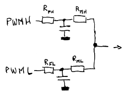
The circuit consists of two RC-filters, consisting of a capacitor and Rfh/Rfl.
With the various laws of electronics, you can calculate that Vout=(1-C)*PWMH+C*PWML,
with C being (Rfh+Rmh)/(Rfh+Rmh+Rfl+Rfl). In other words, by picking the resistors
correctly, I should be able to get the ratios to about 32:1.
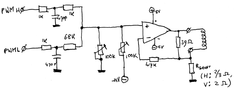
This is the complete deflection amp (for one axis: there are two of these in the
complete circuit.) You can see the PWM-mixer on the right side: the resistors chosen
give a ratio of about 35:1, which for this purpose is close enough. We can't just
feed the output of that into the CRTs deflection coils, though: The coils of a CRT
are fairly wieldy
things, and can require currents up to a few amps to quickly get the electron beam
from one side of the screen to another. To do that, they also require fairly large
voltages: the 3.3V or 5V used by the logic isn't enough for that. And finally, the
deflection of a CRT is current-controlled: the position of the electron beam depends
on the current through the coil, not the voltage over it. That's why the power opamp
is in the schematic. It's a LM675; its pinout is the same as the TDA2030 I used in the
prototype, but it has a higher bandwith.
The power opamp is used as a controllable current source here: it tries to make sure the voltage over Rshunt is the same as the input voltage. Because of Ohms law, the current through the shunt resistor is linearily dependent on the current through the shunt and the coil, so by varying the input voltage, we can vary the current through the coil. All that's left is to center and scale the image, and that's what the two trimpotmeters are for: by pulling the voltage to zero or -15V, the image can be scaled and centered so it appears full-screen on the CRT.
You might ask yourself: what's the 39 ohm resistor parallel to the deflection coil for? The coil itself has a certain induction, but it isn't ideal, and because of some parasitic influences, it can 'ring': when it gets a quickly changing current, it can oscillate a bit. That gives an interesting but not too useful effect... The resistor dampens the coil a bit, cancelling the oscillations.