Power supply
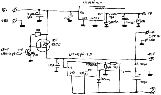
My prototype Asteroids machine needed 4 power supplies: +15V and -15V for the deflection amplifiers, 12VAC for the CRTs high voltage board and 5V for the FPGA board. Getting rid of the 12VAC for the CRTs HV-board was easy: it turned out to run just fine on 15VDC too, so I connected it to that power supply.
Getting rid of the -15V and 5V power supply needed some more work. Eventually, I
found some LM2576-5.0s on a couple of broken PCBs. These are switched mode 5V
voltage regulators. For the 5V power supply, I could just build the schematic
in the datasheet. For the -15V, the datasheet also gave me a schematic I could
adapt to my uses:

On the top, the 5V output, almost completely according to the reference design. On
the bottom, the negative 15V output: the LM2576 in this configuration will regulate
the negative rail until the voltage on the feedback-pin is 5 volt more than what's on
the negative line.. By using a resistor divider, we can make sure that happens when
the output is -15V. You'd expect the divider value to be something like 1:2, but it
seems the IC has also some internal resistors which throw off the values... so I just
fiddled with them until I got the correct voltage.
The inductor and diode used in the negative power supply schematic may be a bit weird. When I first built the DC-DC-converter, I used the same type of diode and inductor as I used in the 5V PSU, but the diode broke a few times on me and the inductor got way too hot. I decided to beef them up a bit and replaced them by a more powerful Schottky-diode and a bigger coil, both ripped from a broken switching power supply. Unfortunately, I don't have the specs of the coil, but I think it's a couple of tens of uH worth of induction.
Apart from the DC-DC-converters, the schematic also contains a P-channel mosfet, plus a transistor to control it from the FPGA. This is a part of my implementation of a so-called 'spot killer'. A spot killer in the original vector arcade games was a small circuit that checked if the electron beam moved around, and if it was in the same spot for too long, it switched it off. The reason was that having the electron beam on one spot for too long would burn a hole in at least the phosphorous layer that emits the actual light.
I've implemented the spot-killer mostly in the FPGA, and in my implementation it kills a bit more than just the spot. Experience learns that when the deflection amps are fed with a non-varying signal, which happens when, for example, the FPGA isn't configured yet, they get fairly hot and can break down. By switching off not only the spot, but cutting the power supply to the complete deflection and HV circuit, I can be fairly sure nothing breaks when my implementation runs into a bug.