Prototyping
Arguably the most important bit of a clock radio is the display: apart from maybe the alarm function, the fact that the thing is a clock means you're usually glancing at it to tell the time. The 90s era 7-segments served me well, but like wired telephones and VHS tapes, it had to go.
LEDs do have some advantages, though. For one, they are their own light source, which is handy for
reading the time in the dark. Moreover, unlike LCDs, there's no 'background light': if a LED is dark,
it emits no light at all. So, maybe a LED display is the way to go after all. Perhaps just having
more of them will suffice?
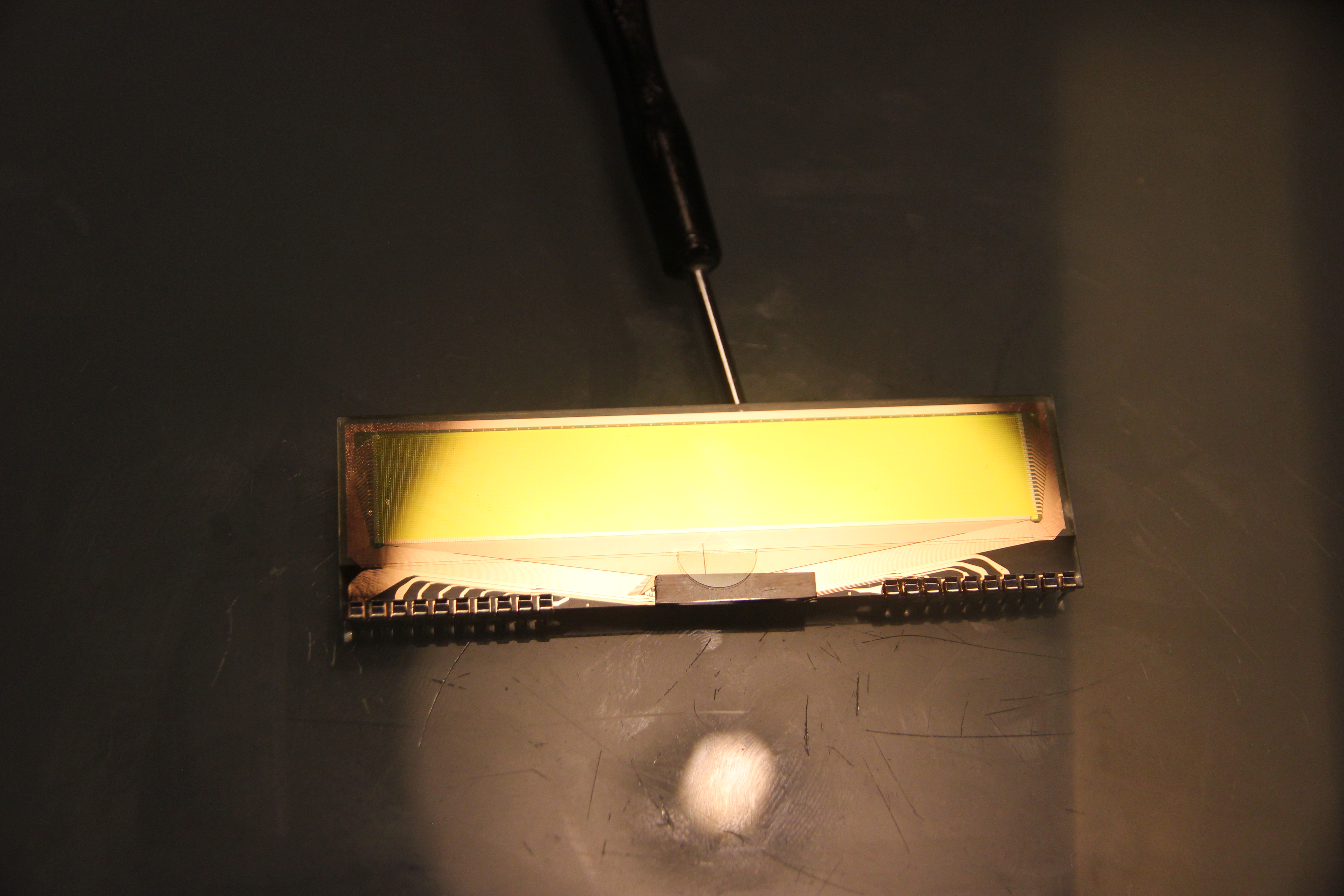
Enter the Osram OS288048PQ33MY0C11 OLED display. Unlike the old display which sported about 30 LEDs, this puppy has 12824 of them, organized in a 288x48 pixel dot matrix fashion. The display is not made anymore, but I still found a couple of them on eBay. It has about the same dimensions as the original LED-display; it's a bit longer, but that can be made to fit. The bad part: I could only get the green/yellow displays and the front of the housing of my clock radio was translucent red; would the OLED display even be visible behind it?
Well, there's only one way to find out if it would work, and that's to mock up something. I ordered
the display and hacked together a quick schematic to try it out. I used a FT232 module in GPIO bitbang
mode to power and control the display. The OLEDs also need an 12V power source, and I hacked that
together by using a PCB from another project which had a boost converter on it.
The software to control it proved a bit tricky because Osram has made a weird design decision with this display. It looks like they couldn't find any monochrome controller chips that could control a 288x48 display, so they took a color OLED controller display that could control 96x48 RGB pixels. They then connected all the monochrome pixels of the display as if they were R, G and B subpixels. This makes controlling the display a bit tricky, but the advantage is that you do get 5-bit grayscales per pixel.
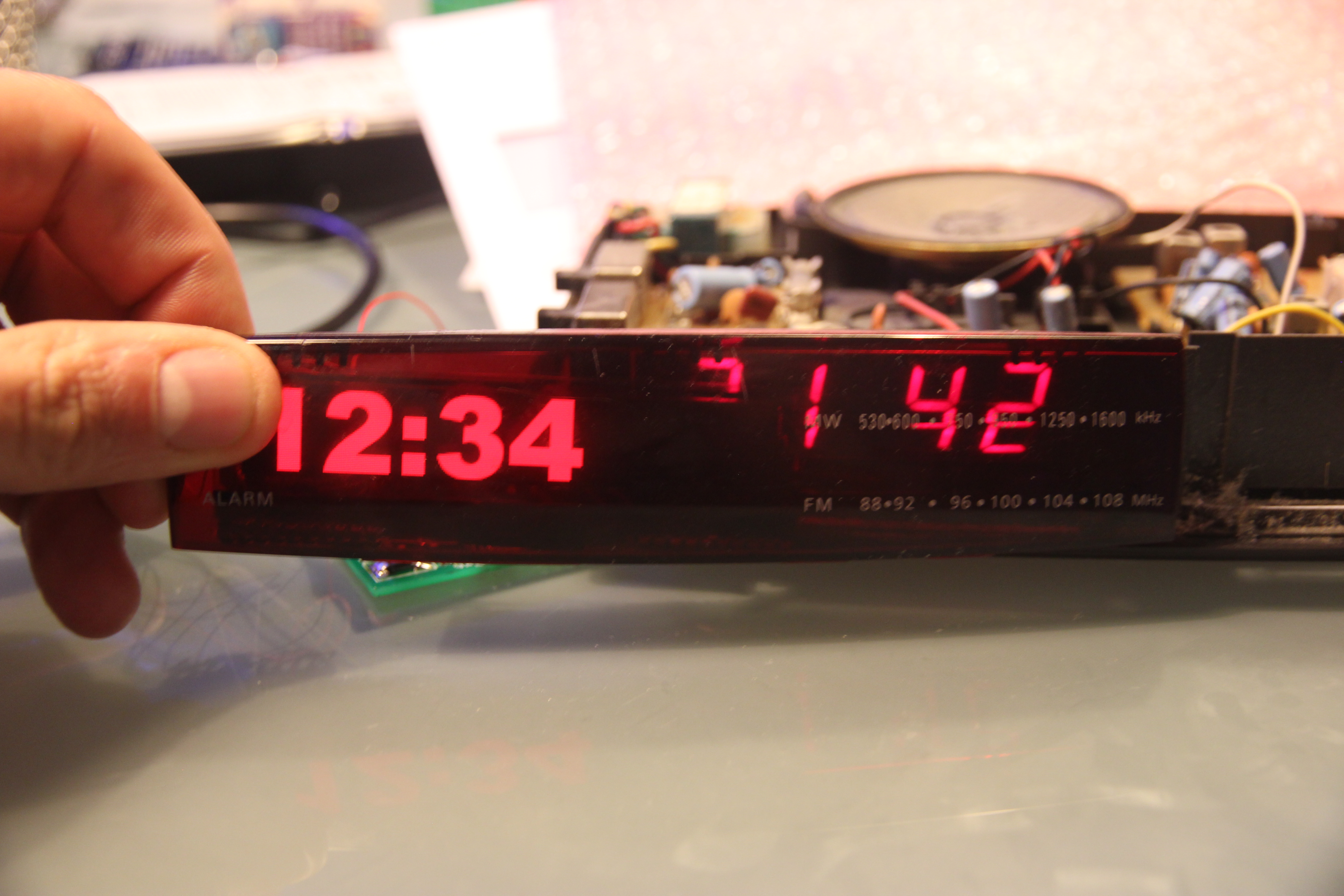
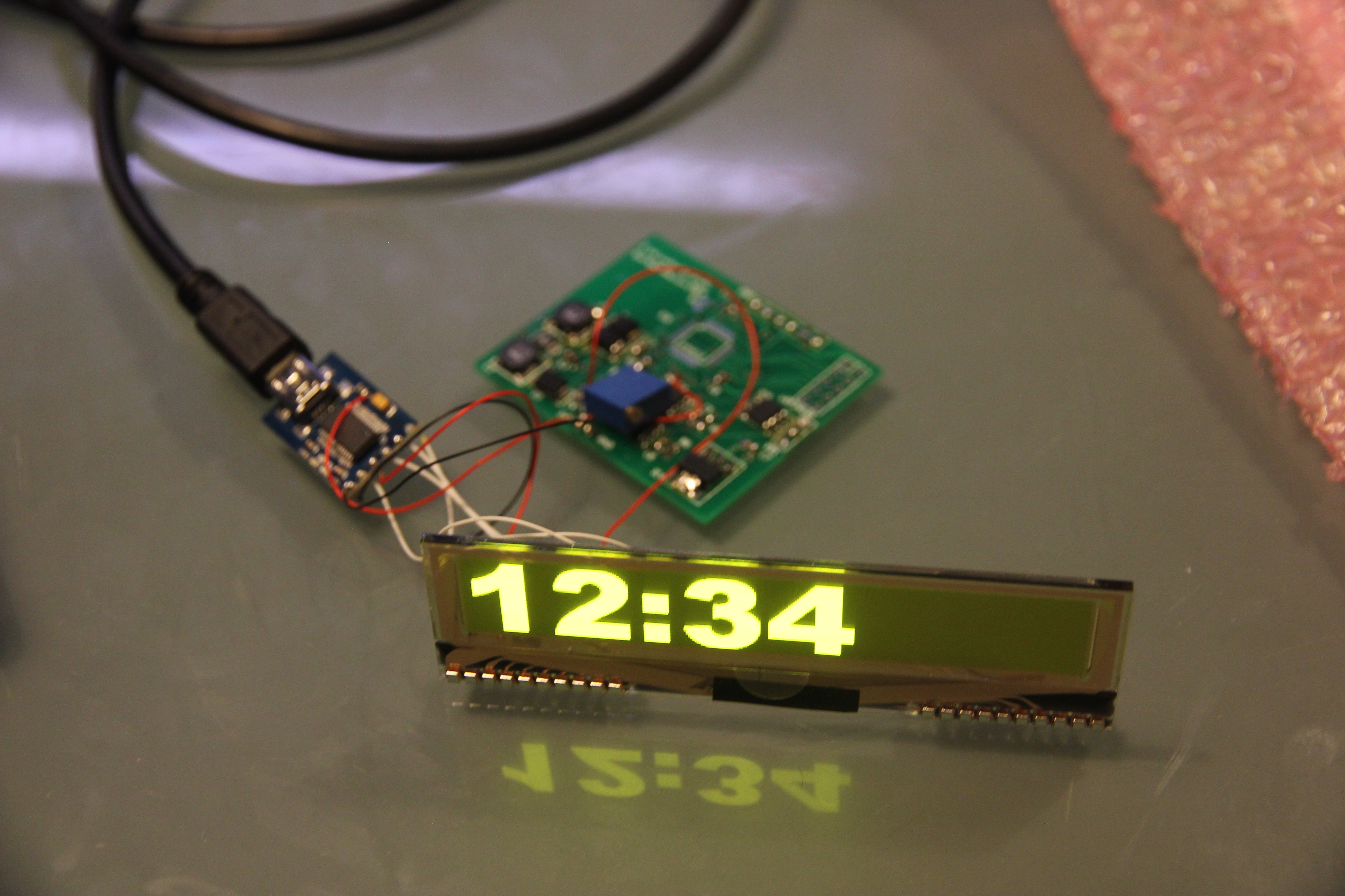
The end result didn't look half bad: although a fair amount of light is lost by sending it
through the translucent red bit of plastic, it doesn't make it any dimmer than the original
LEDs.
I also would need to do some other experiments: What SoC would be useful for driving this? Could I
re-use the old power supply? How would I connect the existing buttons? I decided to whip up a quick
prototype to investigate those questions:
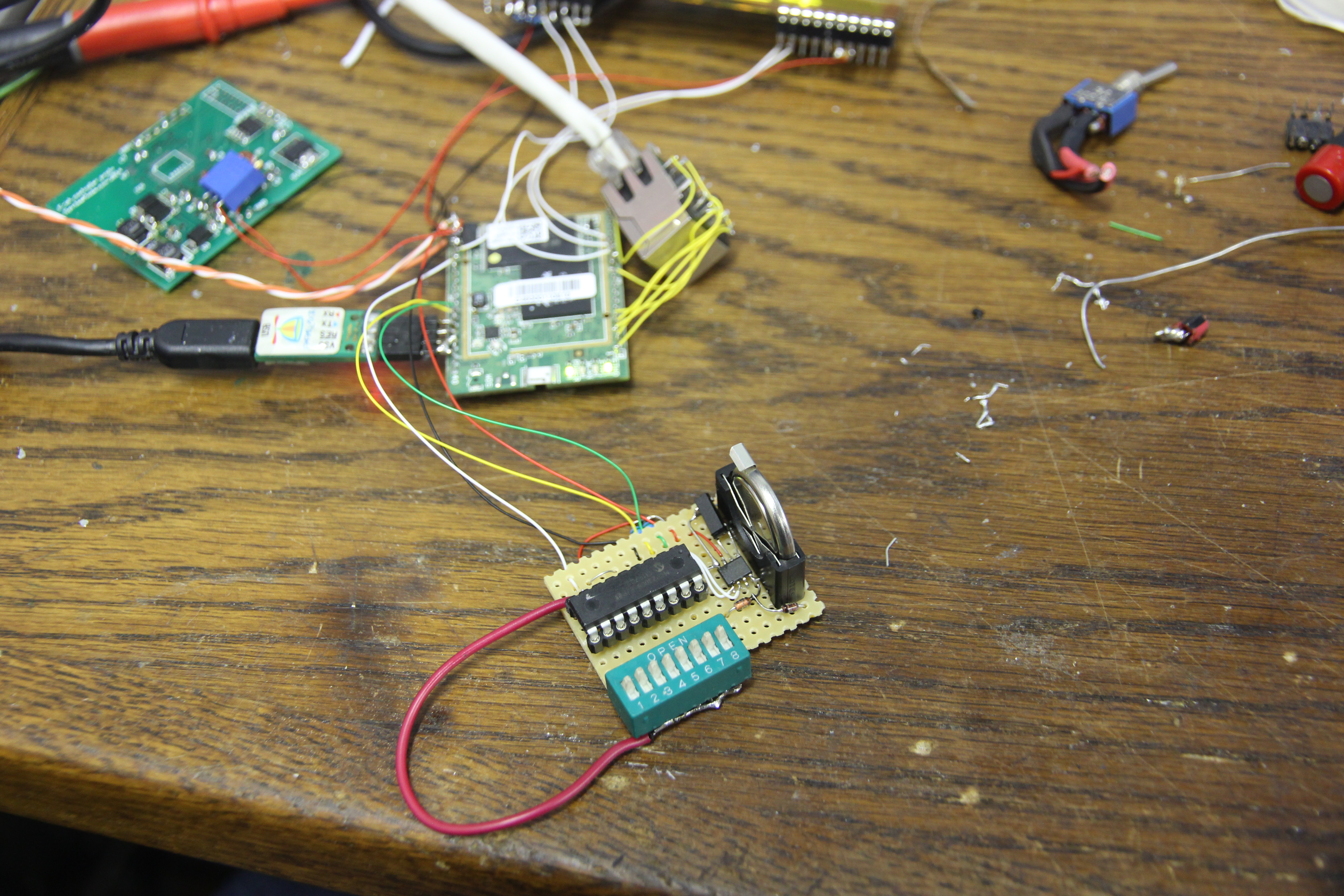
The mess you see here centers around a Carambola Linux-module. I've used these modules before: they're
basically router chipsets consisting of a 300MHz MIPS-processor, 32MB of RAM and 8MB of flash
and integrated WiFi and Ethernet. They run OpenWRT as the OS. They actually are superceded by the
Carambola2 which is more powerful, but I still had some of the old modules and they're
capable enough for a clock radio.
Connected to the Carambola is, ofcourse, the OLED display, here just visible at the top of the photo. It uses the SPI pins of the Carambola so the Carambola doesn't need to bitbang every pixel into it. Connected to the Carambolas I2C port is a small PCB. The PCB contains a PCF88563 real time clock chip, some battery backup for it and an MCP23008 I2C GPIO expander. The GPIO expander is connected to a bank of dip-switches; these simulate all the buttons and switches available on the real clock radio.
Now I could start to develop the drivers for the hardware: I wanted to do this 'the right way', meaning every peripherial would get kernel drivers and the userspace could remain mostly hardware-agnostic, or at the very least would not need to bitbang protocols by itself. For the OLED-screen, this was the most work: I would need to develop a framebuffer driver for it. Fortunately, this is not the first time I have done this. I also would need to have support for the I2C RTC and GPIO expander, plus the buttons that would be connected to the latter. This wasn't too hard: the kernel already has drivers for everything and just needs to be told how the hardware is hooked up to the Carambola.

Another thing that needed hooking up was the power supply. I was planning on using the original
transformer as the power source: I couldn't find a nice switched-mode powersupply that would fit in
the case in a safe way. I also wanted to keep the exterior original as much as possible; this meant
adding a wall wart would be out of the question. The transformer gave out 6VAC and 4VAC, both voltages
I couldn't do much with. I decided to connect them both in series and add a voltage doubler circuit,
giving me about 28V. This then fed into two switched mode regulators, for the 3.3V and 5V power supply
rails. In this prototype, the 12V for the OLED screen still is generated with a boost-converter from the
5V line.
In the end, I ended up with a Carambola that knows the time on boot-up, happily uses the OLED display
as its console and the 8 dipswitches as the keyboard keys A till H:

This would be useful enough to start working on the final hardware.