Building it
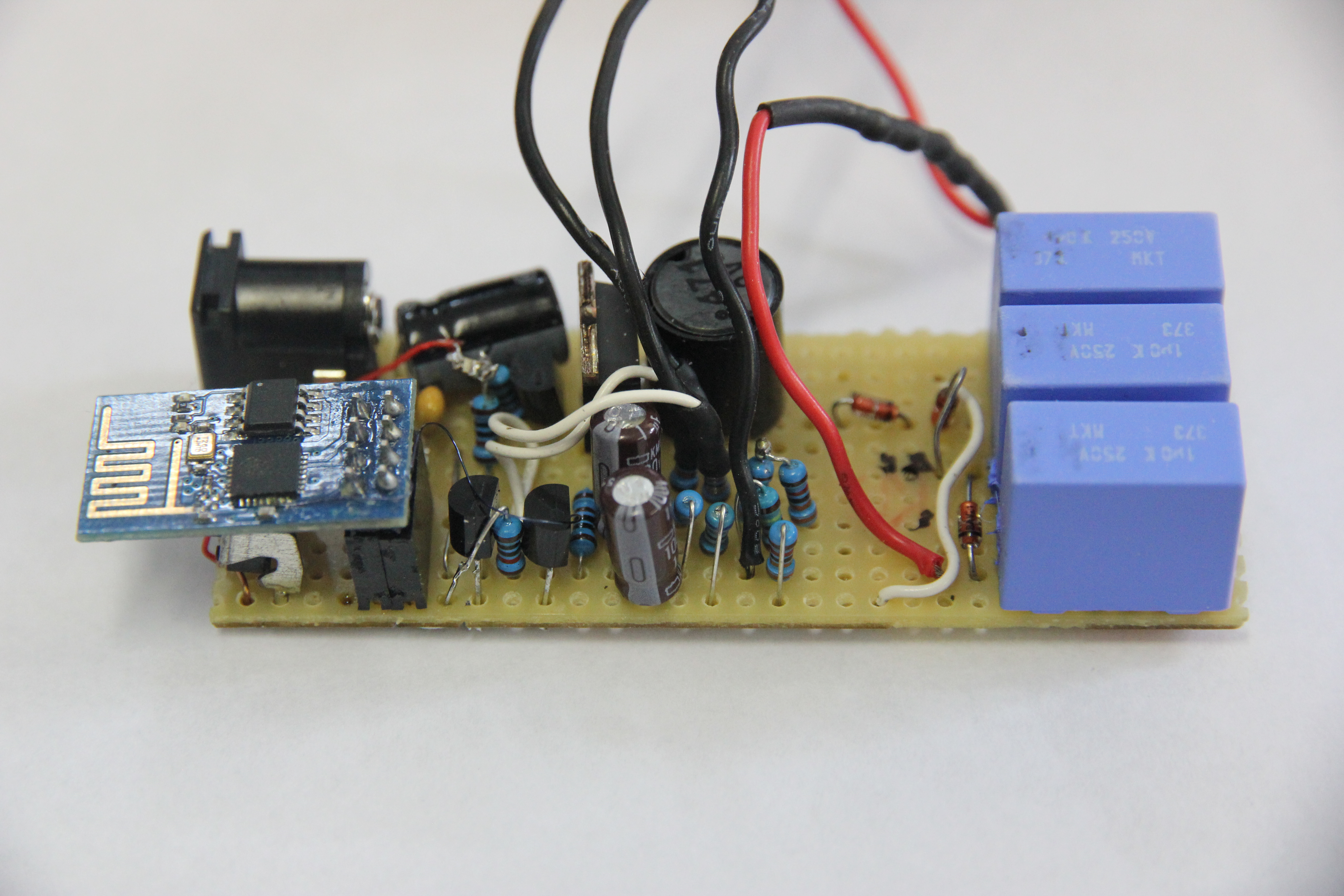
Because this is only an one-off build, I decided to do it on prototyping PCB using standard
through-hole components. This is how the PCB ended up looking. I tried to put the HV section
(with the big 1uF capacitors) on the right, separated from the low-voltage electronics.
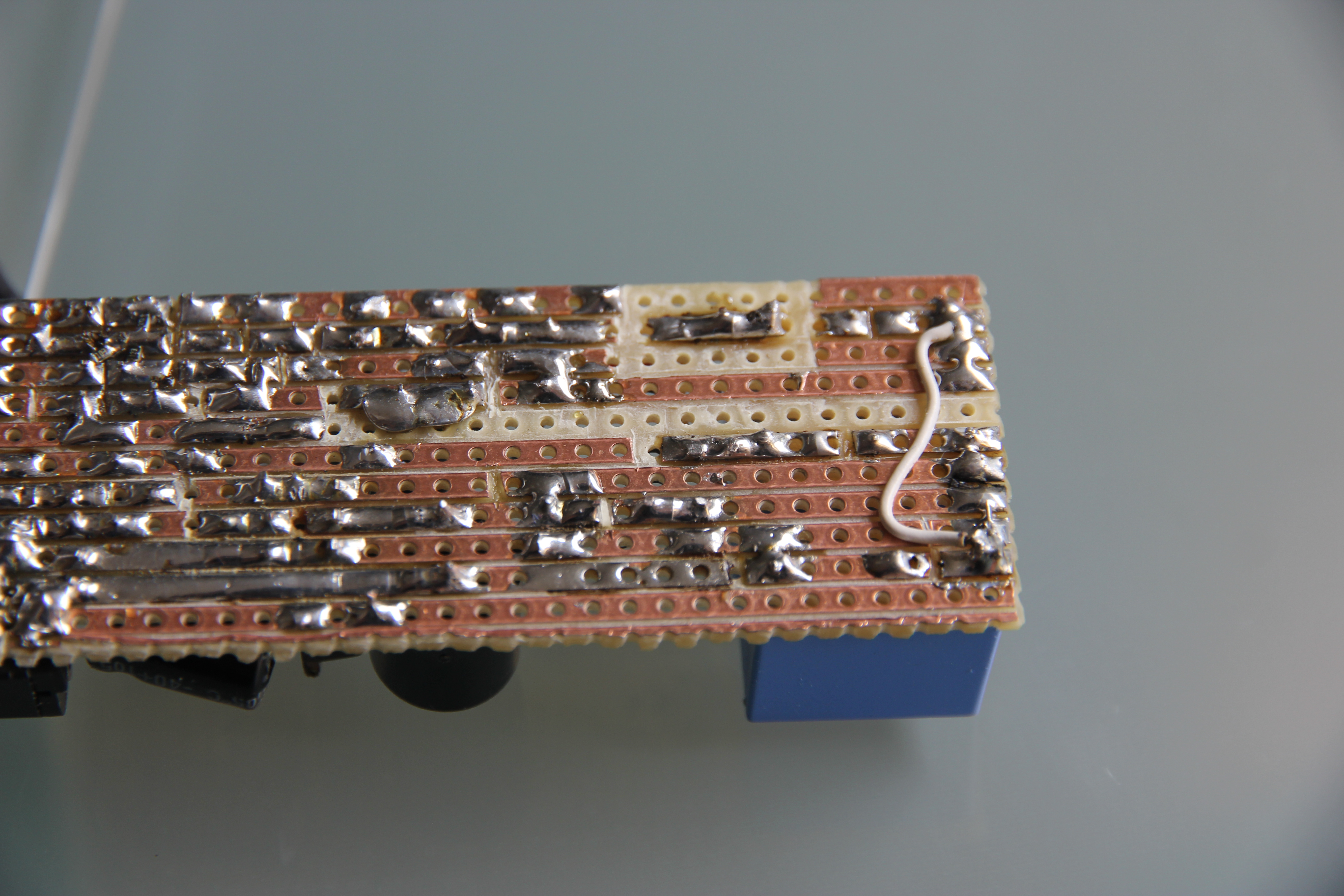
This is the bottom of the PCB. Because around 400V is generated and I don't want to have
that jumping over to the digital parts, I made sure to remove enough copper on the bottom
side to prevent the high voltage from arcing over.
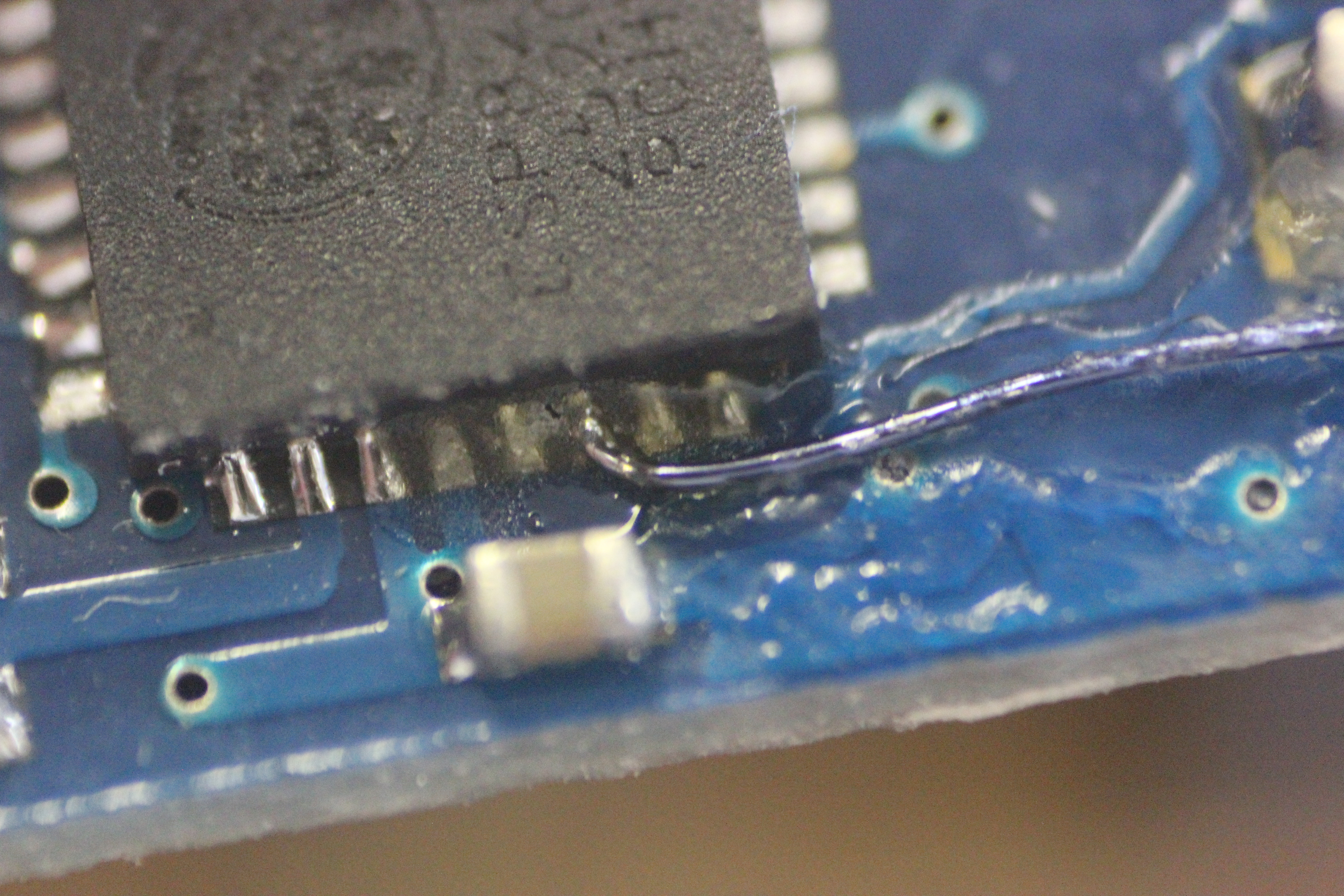
Normally, an ESP01 module does not have the TOUT pin I need to read out the ADC value. I fixed
this by soldering a thin wire straight to the ESP8266 pin and fixing it with superglue.
It takes a fairly steady hand and a small point on the soldering iron, but with some
flux it's pretty easy to get it on.
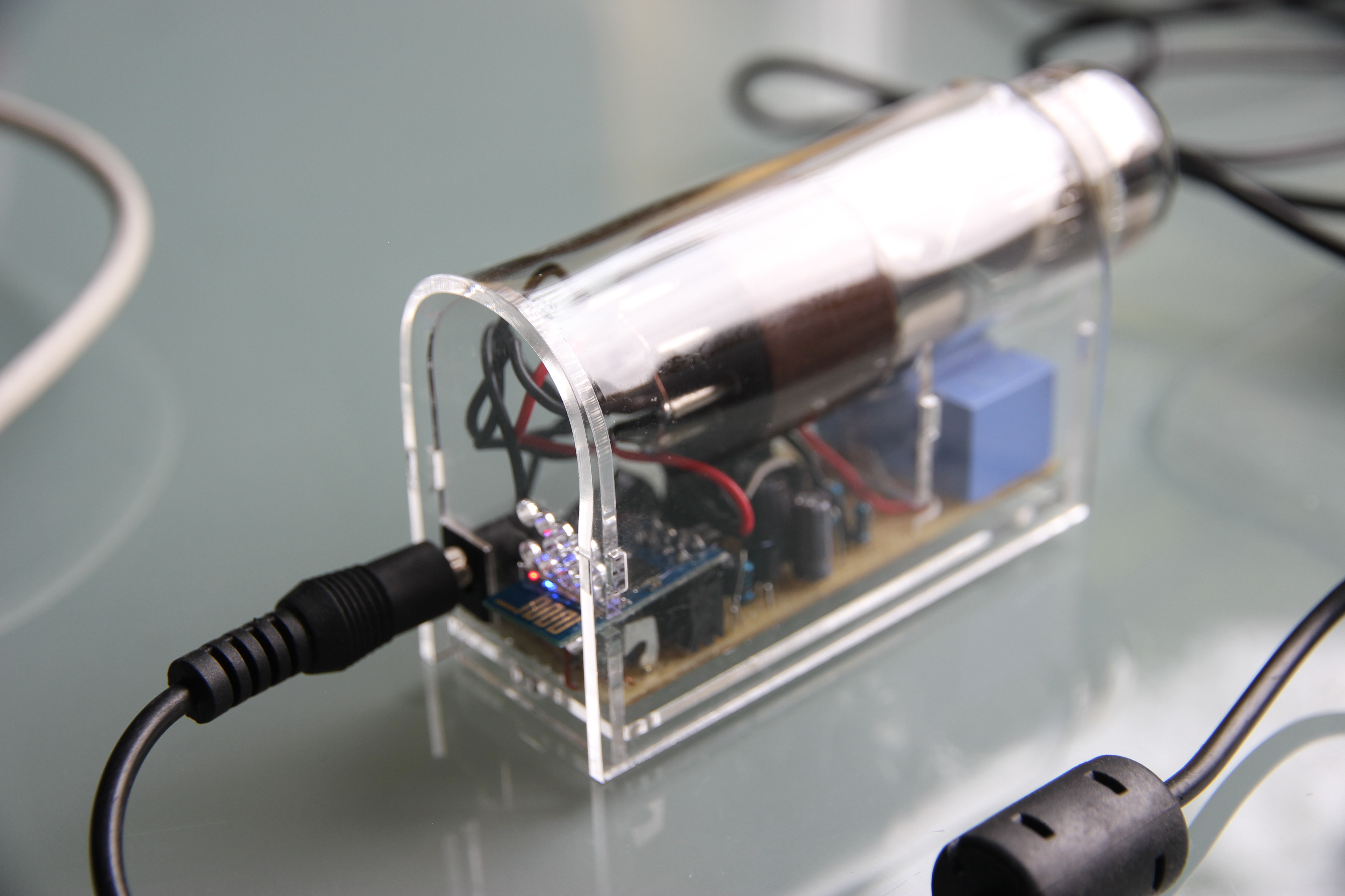
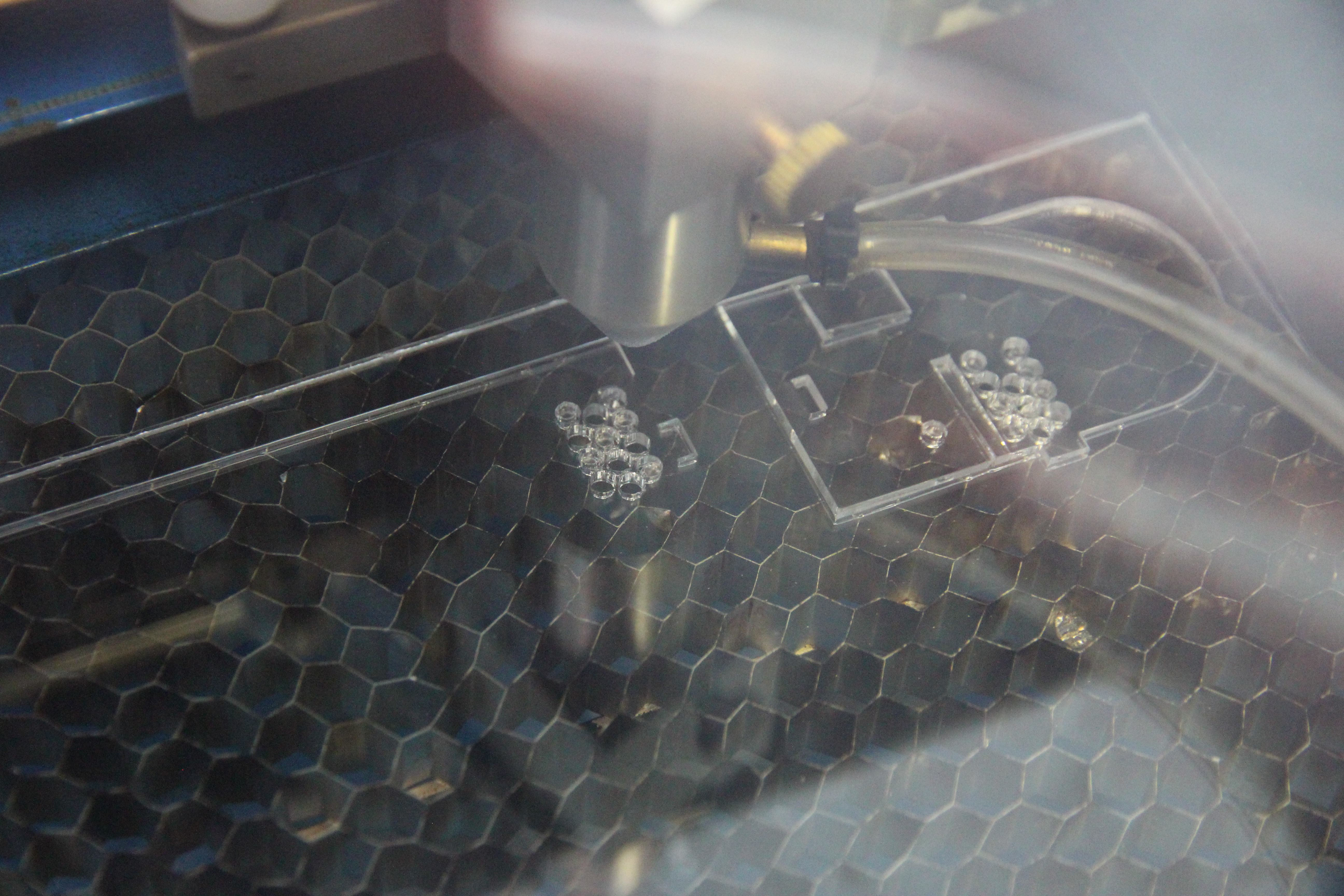
Ofcourse, this project needs a nice case: both because a stack of parts looks quite ugly but
also to reduce the risk of people touching the high voltage capacitors. I whipped up something
in Inkscape and sent it to my lasercutter, which then happily cut out the parts for me.
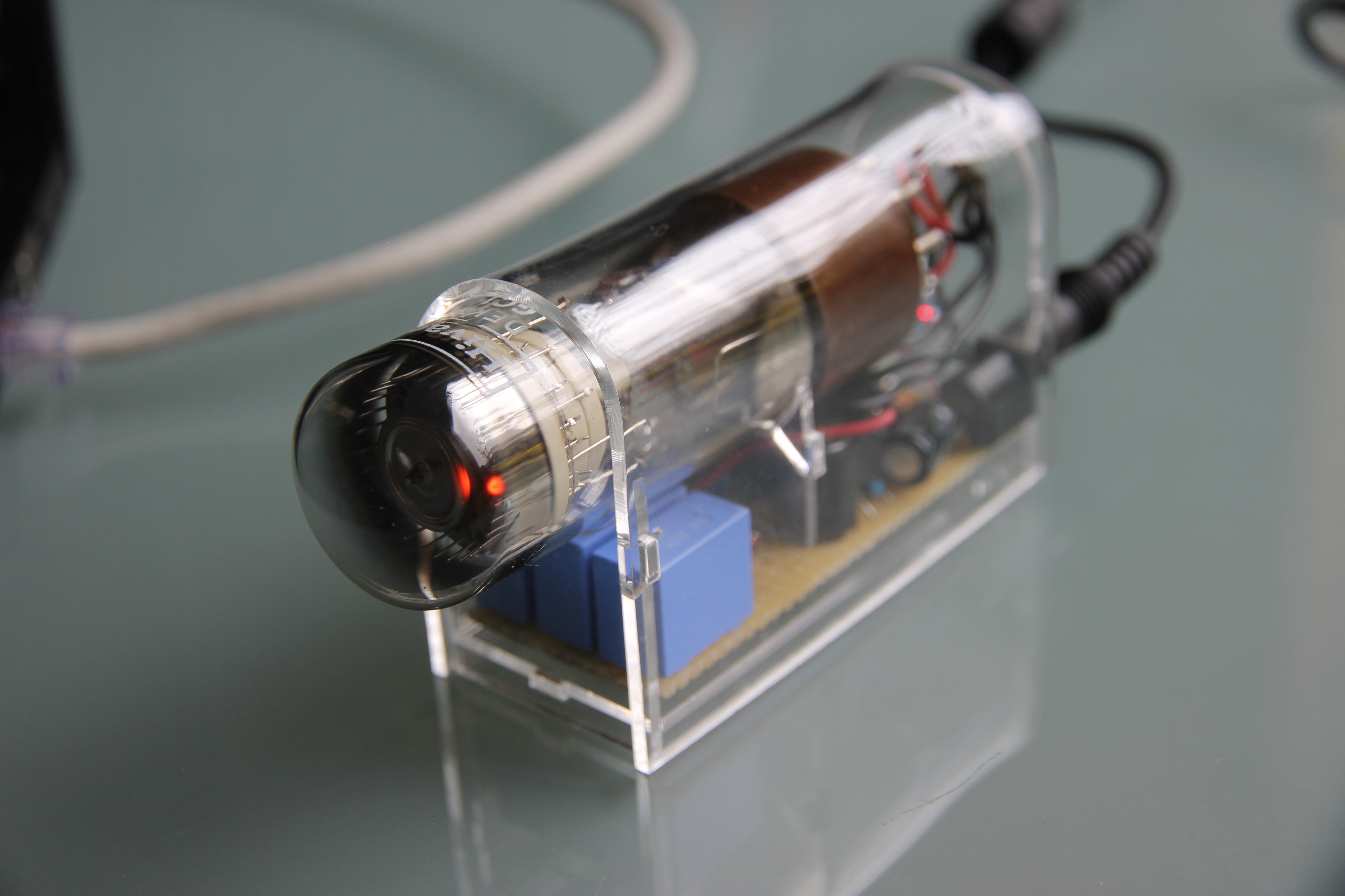
With the pieces in hand, some assembly was needed. Most of my design is press-fit, but the top
part requires me to bend the acrylic over to follow the curve of the tube. I did so by heating
it with a heatgun, then quickly bending it while it still is hot. The end result isn't entirely
perfect but is good enough: the final product doesn't look half bad.
On the back, there's some ventilation holes, a hole to push the button through and the 12VDC connection.
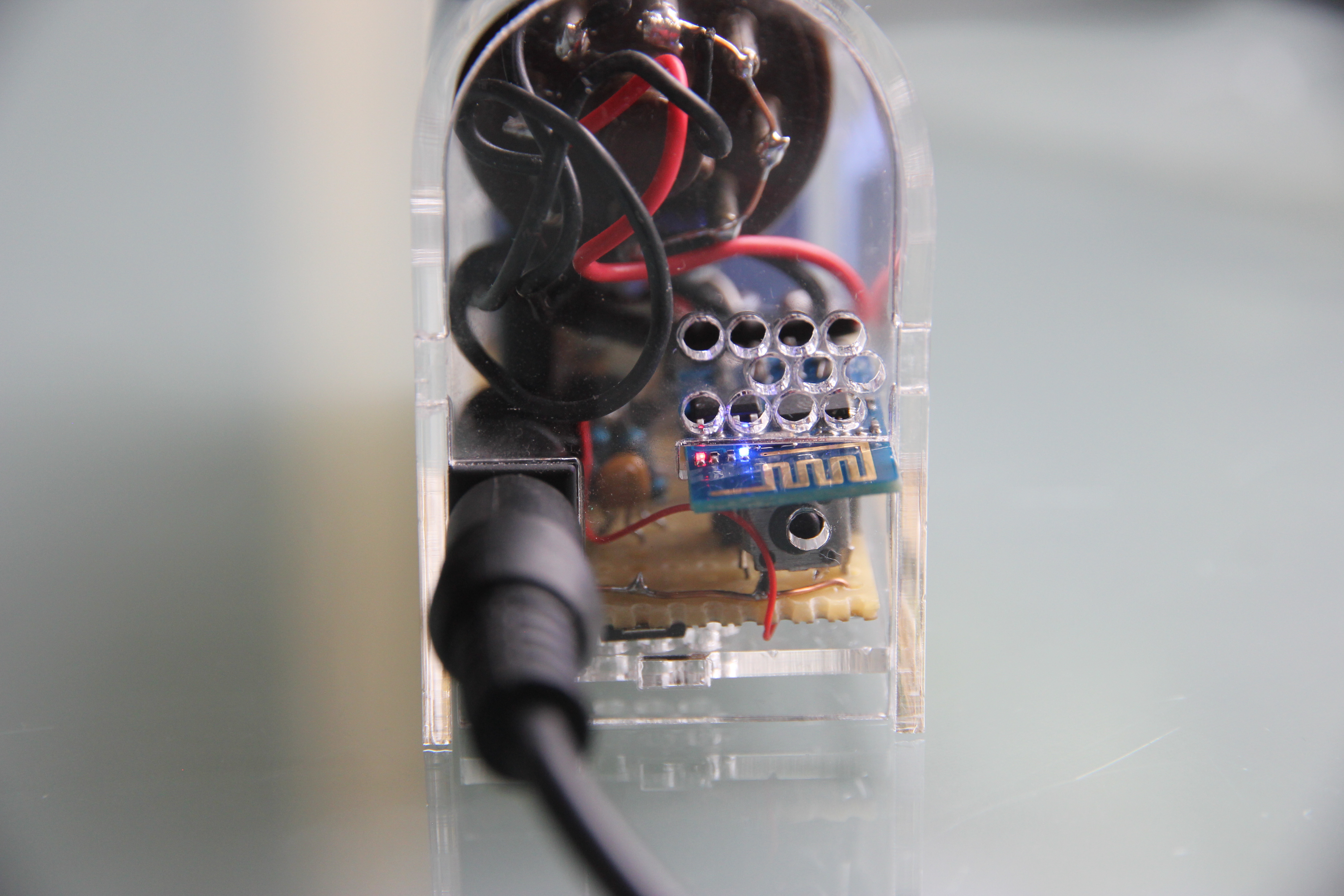
Acrylic is transparent, so you can still see the entire PCB and all the parts.