Second attempt
A while later, I decided it was time again to re-start the project, this time using a different approach: instead of trying to find working timings and connections by brute-forcing many different ones, why not see how a functional device does it? I went online and bought myself a broken Sony PRS-505, thinking I'd have an extra screen if the electronics were broken and somewhere to put one of my spare screens in if the display was broken. When I got it, all it seemed to have was a dead battery; hooking it up to a lab PSU made everything work. Win!
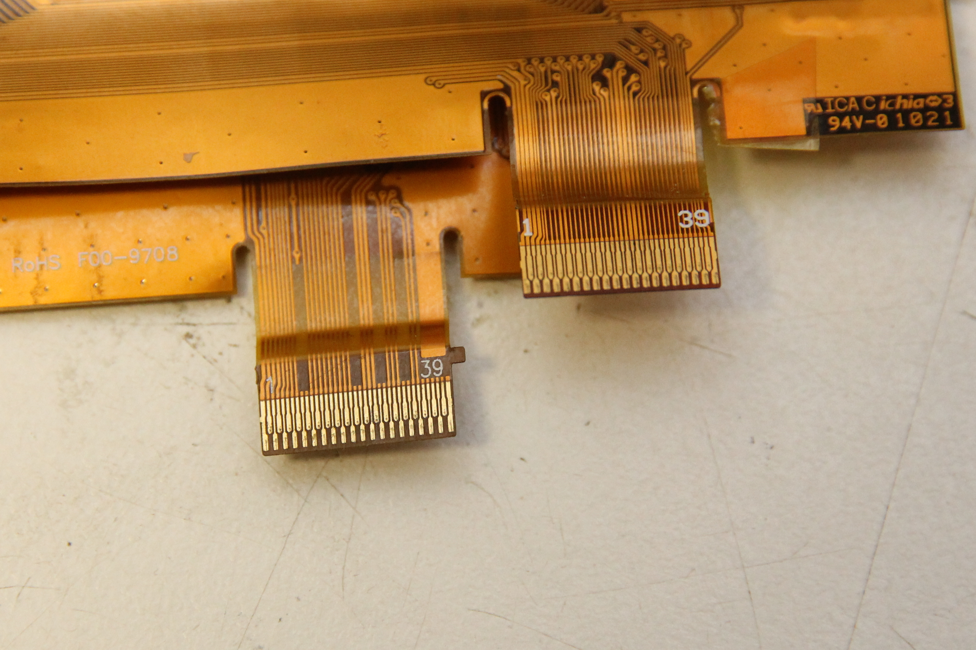
Now, how can I see how this thing manages to control its display? The ribbon cable to the E-ink display has 39 teeny-tiny leads; putting a test probe on those was out of the question. The service manual of the E-reader provided the solution: Sony has been kind enough to connect every interesting signal to a test point. I could happily solder leads to that and get to the signals. I also happened to have bought a shiny new Rigol MSO1074Z mixed signal scope. This scope has an 16-channel logical analyzer included. Time to measure some signals!
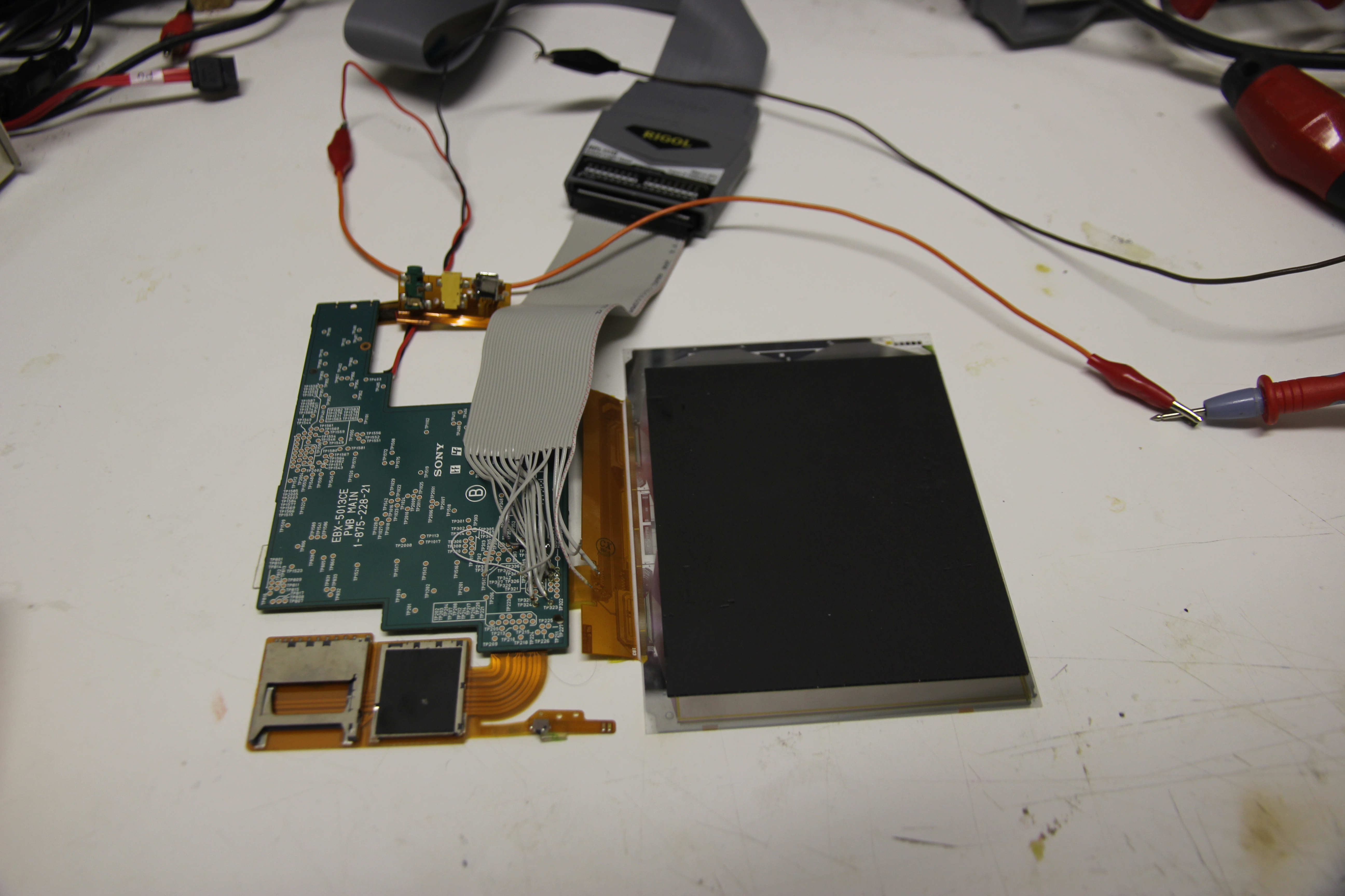
I hooked up an old floppy cable to the logic analyzer pod of the scope, and soldered the relevant wires
to all the test points of the PCB. All the control signals and two of the data signals were brought into
the oscilloscope.

Here's a view of one complete screen refresh. You can see it starts with OE and GMOD going high to tell the
screen it should enable its output drivers to actually move the electrophoretic particles, then SPV
pulsing low to indicate the first line will be clocked in. After that, the actual data gets sent; we're zoomed
out too much here to see the details. Nothing too different from what you'd expect here.

This is zoomed in on a single line of data. There's data being clocked in on the edges of the CL
pins; because it's a lot of data, the CL signal is one white block here. After all the data is clocked in,
CKV will pulse low and LE high to actually send out the data to the screen.
There's something interesting happening here. The CKV, LE etc signals are what we expect, but
the CE2 and CE3 lines weren't mentioned as active signals in the E-ink datasheets that
are on the internet. They are actually active on this E-ink reader. What's going on here?
Some sleuthing later, it seems these lines select different source drivers to send the data to. The
intent of this probably was to make a single controller capable of driving multiple displays, or
maybe larger displays with more source driver. The use of these lines seems to be deprecated: the
one display that did work in my previous setup didn't even have them:
So why is the controller on the E-ink display toggling these lines? Probably because it's programmed to
send out the data for multiple screens or source drivers. Because E-ink is quite slow, sending out
the extra data wouldn't have any effect on performance, which is why I guess they left it in.

Just for completeness, this is the signal zoomed in further. You can see the clock going up and down
while the data is shifted into the source drivers.
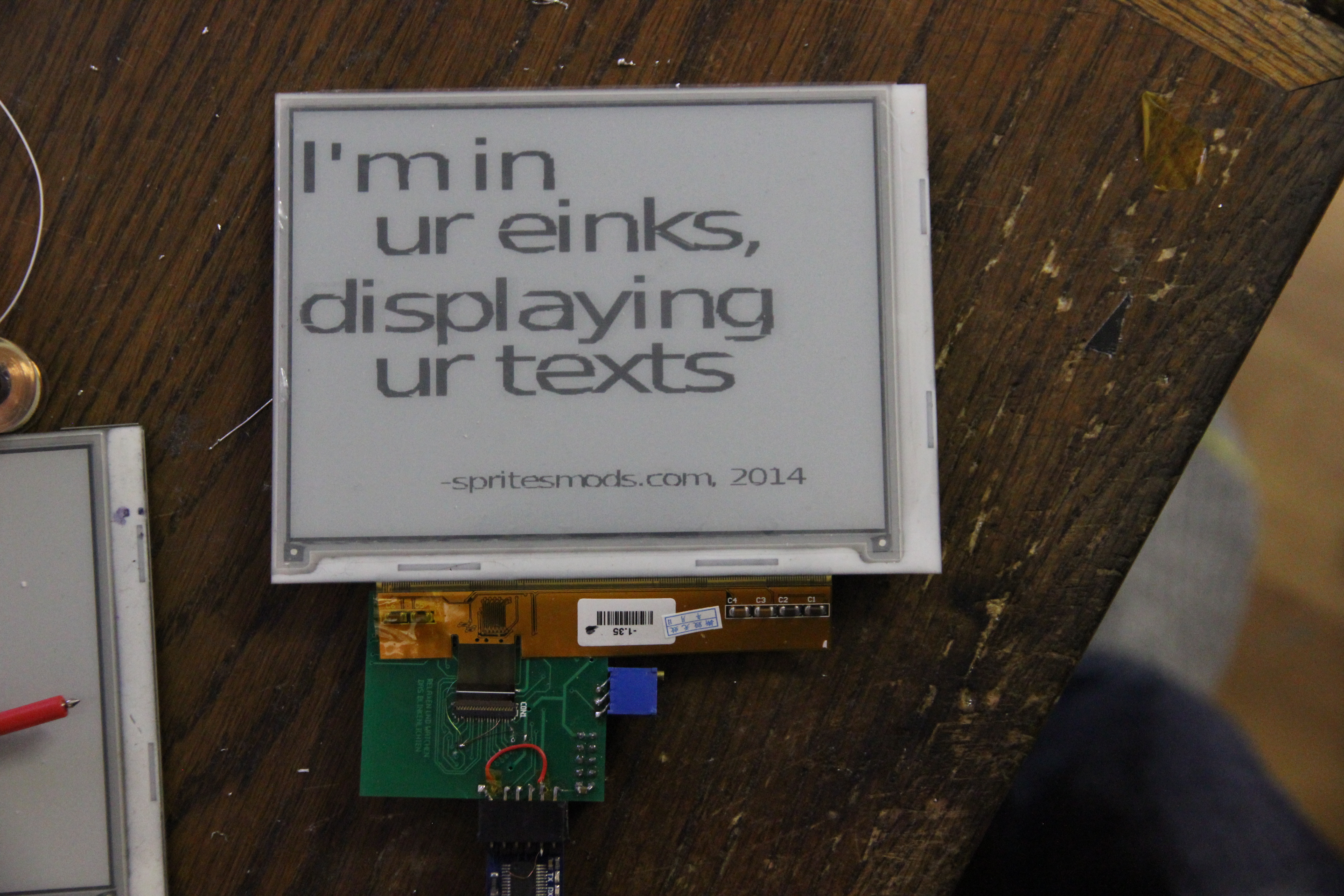
With this information, I could try and replicate the signals the E-book reader sent. With some fiddling,
that resulted in actual information being displayed:
So now I knew how the display works, I could move on to make the final device.