Hardware
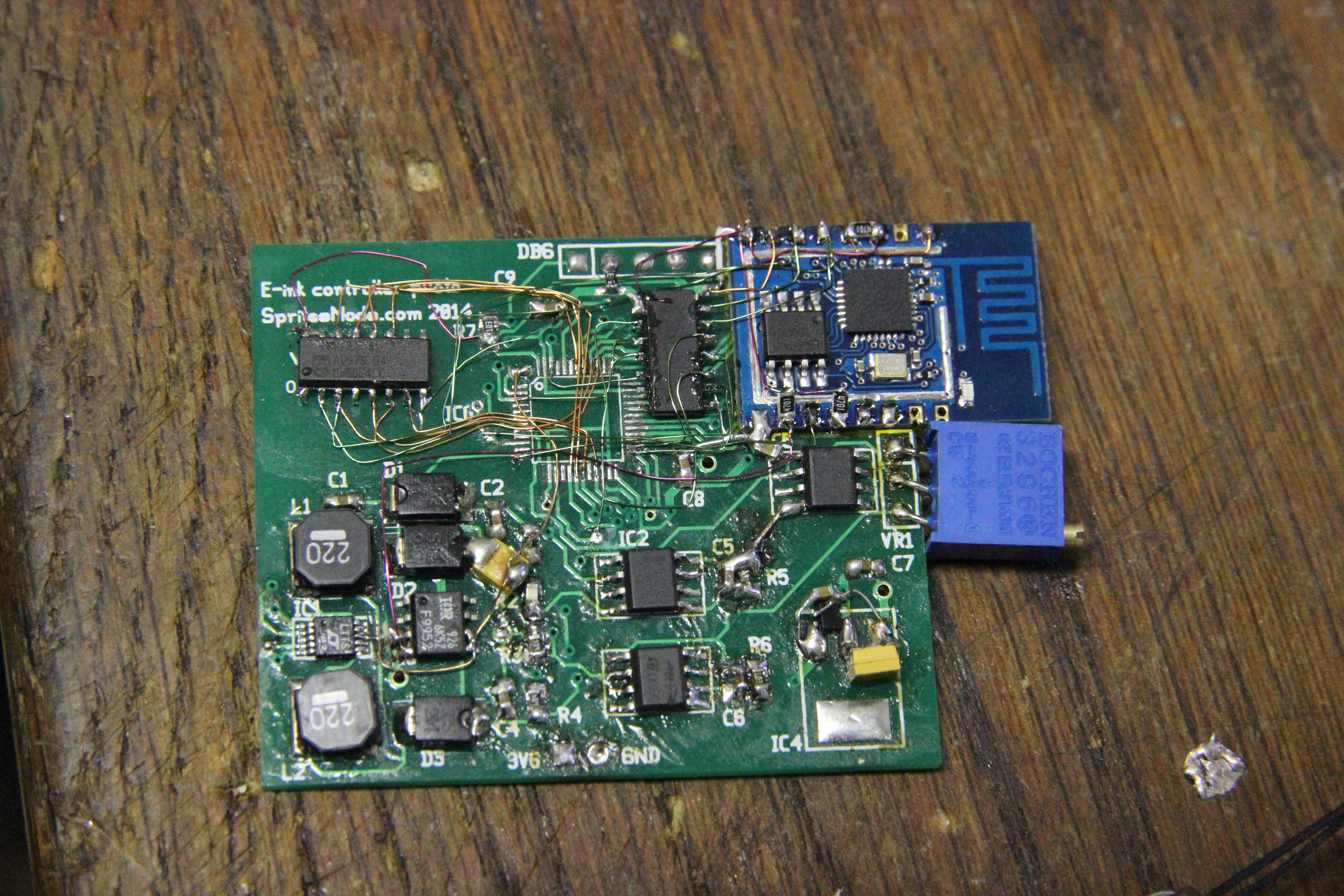
First of all, I needed a new PCB. The old needed way too many hacks and bodge wires to work and had the E-ink connector in an inconvenient place if I wanted to place the PCB behind the E-ink display. Moreover, while I was planning on using an STM32L1xx processor as the brains with an nRF24l01 as the communications channel, in the time it took me to debug the E-ink interface the ESP8266 came out. If you don't know this device: it's a WiFi chip with integrated 160MHz 32bit CPU and some RAM. Combined with some flash, it's a complete integrated WiFi device: only apply power and you can do things on the 'Net. Even better, modules containing this chip, the required flash and an antenna go for about EUR3, which is cheaper than the combination of STM32L1xx and nRF24L01 module.
So in the end, this is the schematic I used:
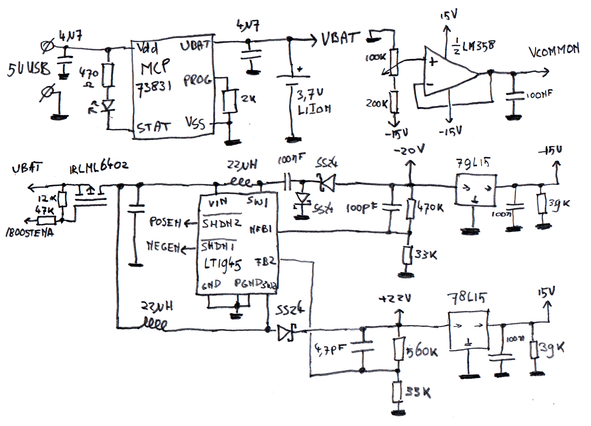
To generate the various voltages, I have used an LT1945. This tiny chip can generate the required 20V
and -22V from the 3.7V LiIon power supplies. A classic 78L15 and 79L15 pair then convert this into
+15 and -15V. A variable resistor and an opamp generate the display-specific Vcommon voltage. Power
to all this is gated by a P-channel MOSFET, so when the device is sleeping, no energy can seep away.
Because having a separate charger is a pain in the ass, the board has an integrated charger for the LiIon battery in the form of a MCP73831 LiIon charger IC. This little IC, when connected to a 5V power supply, will handle all care and feeding requirements of the attached LiIon cell. The device is set to pull a maximum of 500mA from the 5V supply, so I connected it to a mini-USB connector. Technically, you can't draw more than 100mA from the USB bus without negotiating, but so many devices do this anyway that every port nowadays can handle a 500mA current draw without negotiating just fine.
The design has one drawback, and that's that the high-voltage generating parts are pretty inefficient: when I turn on the boost converter, the battery gets loaded with almost 100mA, even without the E-ink display connected. How is this possible? Mostly, the 78l15 and 79l15 are to blame. The technology of these parts is pretty old, and they eat up about 8mA to function. That's not that bad, right? Well, these parts draw their power from the +22V and -20V generated by the switch mode converter. A converter like this will pull a current on it's power supply that's equal to the load on the output side times the ratio of the input voltage divided by the input voltage. For the +22V rail, assuming a 3.6V LiIon battery, this ratio is (22/3.6=)6.1x. This means the trickle of 8mA on the 22V rail translates to an (8mA*6.1=)49mA torrent on the battery! The numbers for the -20V are about the same, totalling the current spent on just getting the +15/-15V at almost 100mA.
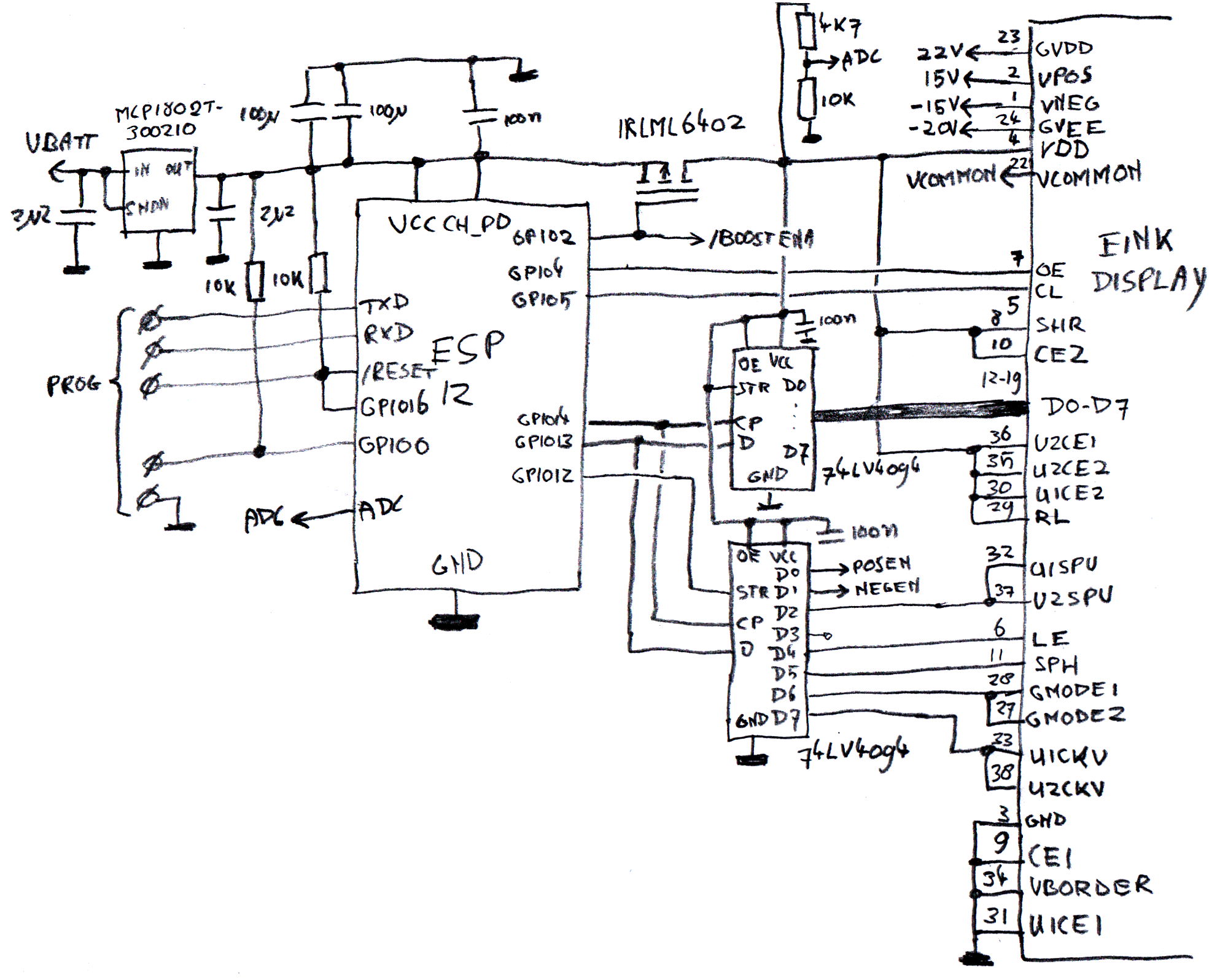
As you can see, the logic part of the schematic has an ESP12 module as the brains of it. This is one of t
he aforementioned modules containing the ESP8266, some flash and a PCB antenna. Because the chip
doesn't have too many I/O pins, the bulk of the E-ink lines are connected to two 74LV4094 shift
registers. The ESP8266 has an integrated SPI master, so shifting bits into these registers should go
quickly enough. For power, there's a 3.0V linear regulator: the 4.2V that can be on the LiIon-cell when
it is charging is a bit too much for both the ESP as well as the E-ink display. The 3.0V to the
E-ink display is gated by a P-channel MOSFET too so no current can leak away through that part when
it's shut down. Finally,
there's a small resistor divider connected to the ADC pin of the ESP so it can detect the state of the
battery.
Ofcourse, the change in schematic warranted a new board. I designed a 5x5cm dual-sided board, with all the components on the top so the back could be stuck to the E-ink display. I also made sure that the debug port, WiFi antenna and USB connector stuck out to the side if the board was connected to an E-ink display.
But we're not done yet. The board doesn't have a power source or an enclosure yet.