Conclusion
So, now I had a nice display which could just hang on my whiteboard and display interesting
stuff for a long time without being recharged. How long is that time? Well, it obviously
depends mostly on how often the display is refreshed: thanks to the design and the low power use of the
ESP8266 chip when it's in deep sleep, if the screen is idle it only uses 50uA or so. How many
power does it use when a refresh is occuring? That's hard to say: due to the WiFi radio, refresh
activity etc all having their own timings and the refresh only taking ten seconds or so, it isn't
easy to just put a multimeter in series. With a scope, it's easier to measure. What I did
is put an 1 ohm resistor in series with the battery, and stuck two channels of my scope onto it:
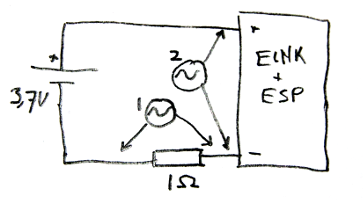
I measured the voltage over the resistor on channel 1 of my scope (shown in yellow). Due to the resistance being
exactly 1 ohm, 1 volt on the channel equals 1 ampere over
the resistor. I then used channel 2 (shown in blueto measure the remaining voltage into the device. On my
scope, I enabled the math channel (shown in purple) to be the multiplication of the two channels. That waveform
thus showed the power usage in (volt * ampere =) watt. Finally, to calculate the impact on the battery,
I told the scope to measure the area under the math waveform. This is equal to the power used, measured
in watt-seconds:

It's a bit hard to see, but the purple letters in the right bottom of the screen indicate the update
used up 4.25Ws of power. If you throw that and the specs of the battery into Wolfram Alpha, you end
up with a
calculation
that tells you the display can be refreshed about 9700 times before the battery runs out. If you
refresh the display every half hour, this means the battery should last you 202 days. This is
a bit optimistic; bad WiFi connections, WPA, cheap batteries and the circuit not completely being able
to drain the battery will in practice lead to a battery that's empty sooner, but it gives an indication.
Finally, to show you what the Eink-screen can display, I threw a few webpages at it.
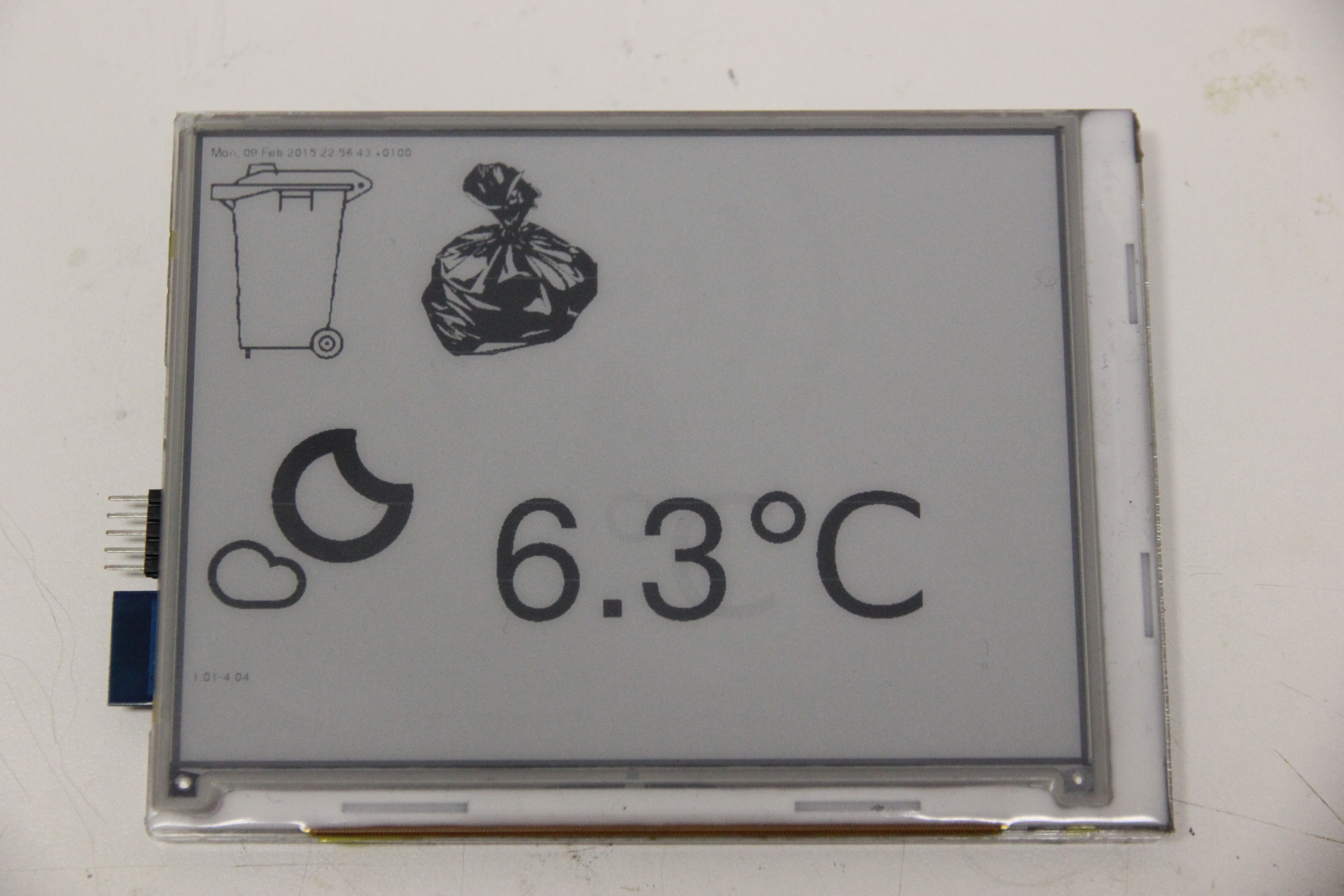
This is my current house display. It shows the weather forecast and what garbage needs to be taken to the
street. I'm planning on expanding it, but just having these two things already is pretty helpful and
the large icons are well readable from a distance.
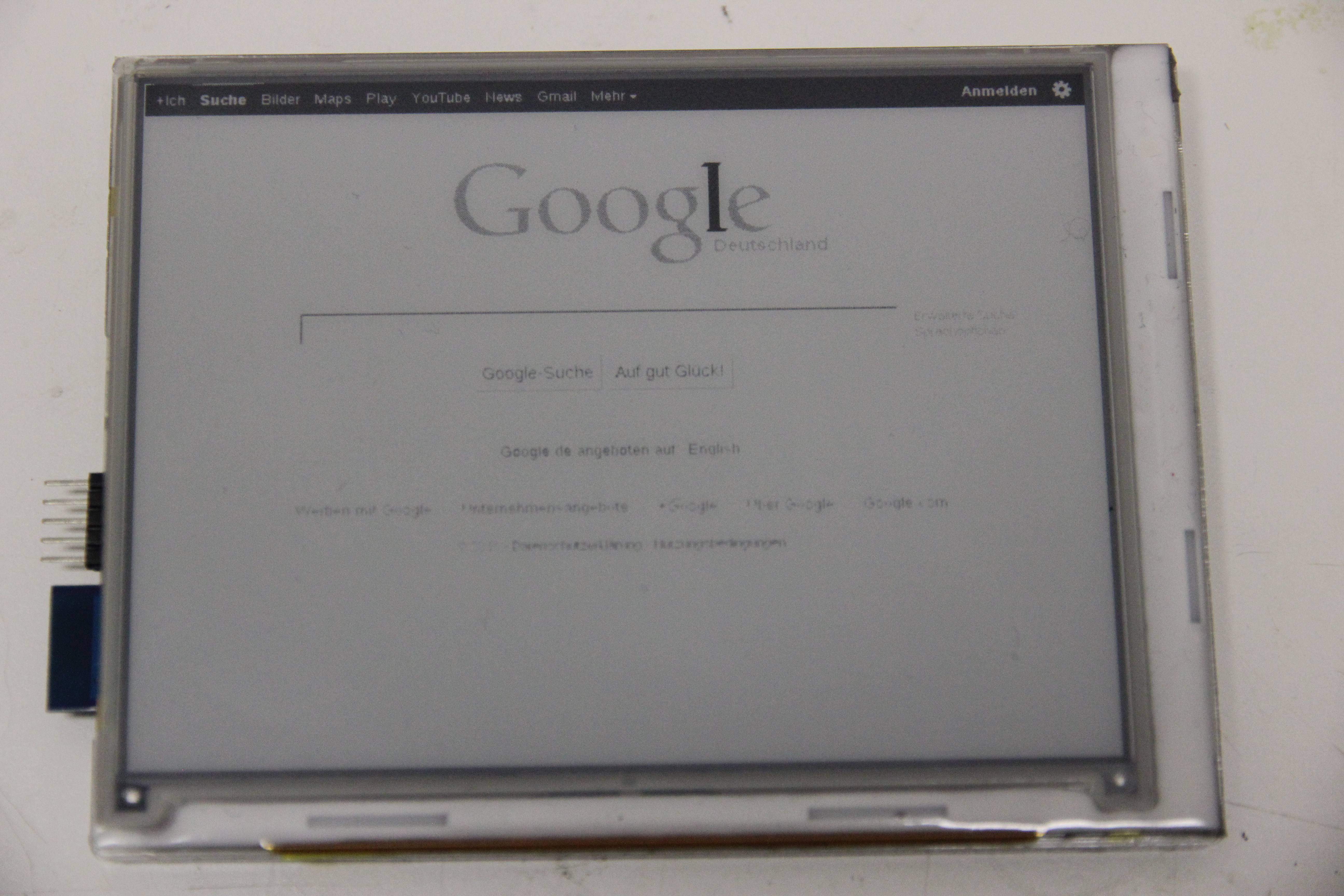
The Google homepage. Small text is readable but not from a distance. The grays in the logo are done by
dithering: for now, the Eink display can only make a pixel black or white. Technically, grays are possible,
I just haven't implemented them yet.
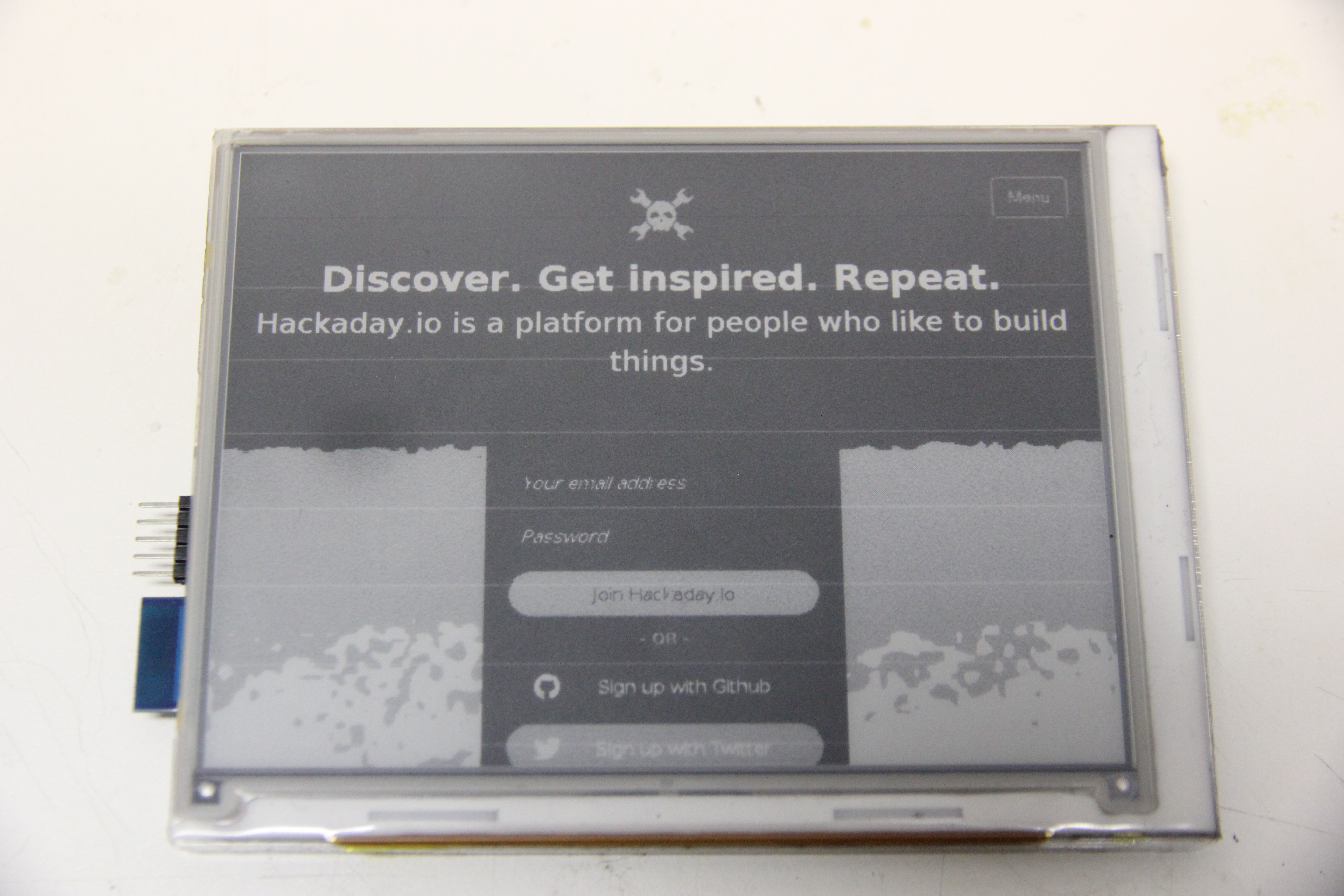
This is the hackaday.io page. It's mostly black, and it shows a
disadvantage of a scheme I use to save power: every time the ESP needs to wait for more data, it cuts the
power to the E-ink display. Unfortunately, it seems that the first line written after it powers the display
up again is a bit lighter, leading to some lighter horizontal lines being visible in black things.
Inception!
As usual, everything I used to make the display is released under an open-source license. The pcb and the lasercut designs are licensed under a CC-BY-SA license. The firmware for the ESP8266 can be gotten by cloning this git repository. If you use any of these things, I'd love to hear about it!
« Prev 7
62 commentsHello, you project looks awesome. I just tried to clone your git repository but was not able to find the master-branch? Did you remove it? Thanks a lot.
Hi Spritesmods, I have done all the hardware things and have flashed the board with your firmware. Yet my ED06SC4(lf) just shows some vertical lines only. This may mean the gate driver is not working. I have tried several other waveforms available on the net like one from essentialscrap.com and another one from https://github.com/nbzwt/NekoCal/blob/master/Software/epd.c but nothing goes near to the results achieved with your waveforms. On the hardware side I have maintained -1.35 vCom as described on my panel sticker. also PosV is close to 20V (19.8V actually) while NegV is exactly 21.3V. It seems MCP7802 wont work, the esp not even managed to boot, so I replaced it with NCP4687. Will you please help me to troubleshoot the gate driver?
Hey there. Great project. While I could understand most of the software aspects, I am not anywhere good enough with the hardware aspects of this project. I wish there was something like this I could buy for some bucks. I'd put these kinds of displays next to the door bells downstairs (I live in one of 15 apartments in the house), because they change rather seldom, yet would look very nice AND people with access could use an app or the likes to set up the names next to the door bells. I don't suppose one could buy this anywhere possibly ready-made, right? If I am mistaken, please leave me a message at: divStar at gmail dot com. Thanks! :)
Hi, I cleaned a bit the project files and added a script to setup up to date (01/2017) tools : https://github.com/Oliv4945/eink/ Thank you Sprite_tm for this project !
Any plan to do a version 2.0 with Color E-ink? We have a large four month white board we use at home and I am looking to update it with several E-Ink displays and connect to apple ical or google calendar.
There Is a chance to use arduino as driver? I'm not an hardware "fan".. i do well with coding.. but i will need some help in using arduino as driver.
Please help how to code esp8266 and how to buy the circuit esp8266 with eink? my e-mail : svgrid@gmail.com
This is a really great idea! Thank you for the detailed description of your project.
It is really really great !! Is it makable by a newby ? I'm able to make electronics from the web but don't know how to debug it if it's needed. But it seem that this... Is what I need to put in my house for domotics. With Jeedom, it will tell my when the laundry is done and so much others informations !
Is there anyone who was able to replicate this amazing project using TPS65185 and a micro controller??
Your device is USB powered so why not use a device like this and average your mAH over a period of a given utilization? There are a bunch of similar meters like this - this is not an endorsement for this meter at all. http://www.amazon.com/DROK-Multimeter-Capacity-Voltmeter-Capacitance/dp/B00XL2Y8L6
After reading the very short public datasheet of the gate drivers I might have an idea how the UxCEx pins work. Their name suggest that they are used for cascading multiple drivers together but tying one to GND and the rest to VCC still works so they don't carry any data. I sketched my theory how they work here: http://imgur.com/glHgcFO. The CE pins switch the input of the shift register between the SPV signal or the cascading signal from the previous gate-driver. The MUXes in the image are obviously just symbolic since the signal has to be able to go in the other direction as well if the RL pin is used. I don't have my panel yet, can somebody confirm this? If this theory is right by pulling U1CE1 and U2CE1 LOW and U1CE2 and U2CE2 HIGH the upper and the lower gate driver will be seeded at the same time. That should result in the upper half of the image being copied to the lower half as well. Although if the SPV pins of the two drivers are not connected together on the panel the lower half will not show anything. Also has anybody tried what happens when only one of the GMODE pins is pulled high? The gate driver datasheet says it selects different driver modes (one-pulse, continuous two-pulse, jumping two-pulse) maybe useful for dithering?
Hey joakim. I managed to build it with the current esp-open-sdk (version 1.5.2) but it needed some modifications. Use the espmissingincludes.h from here: https://raw.githubusercontent.com/Spritetm/libesphttpd/master/include/espmissingincludes.h. Since it was from another project you have to comment out the lines following "#ifndef RC_LIMIT_P2P_11N" till "#else" and the closing "#end" and make sure that the *vPort* functions with 3 arguments are defined. Hey joakim. I managed to build it with the current esp-open-sdk (version 1.5.2) but it needed some modifications. Use the espmissingincludes.h from here: https://raw.githubusercontent.com/Spritetm/libesphttpd/master/include/espmissingincludes.h. Since it was from another project you have to comment out the lines following "#ifndef RC_LIMIT_P2P_11N" till "#else" and the closing "#end" and make sure that the *vPort* functions with 3 arguments are defined. Also replace "os_timer_t" with "ETSTimer" in this file. In c_types.h of the sdk uncomment the lines of the following typedefs: uint8_t, int8_t, uint16_t, int16_t, uint32_t, int32_t Replace the calls to os_update_cpu_frequency() in eink.c with ets_update_cpu_frequency(). Or do it the lazy way by adding "#define os_update_cpu_frequency ets_update_cpu_frequency" at the start of eink.c. Add #include "mem.h" bool ICACHE_FLASH_ATTR check_memleak_debug_enable(void) { return MEMLEAK_DEBUG_ENABLE; } to user_main.c as instructed in mem.h for the makefile I used the following settings: XTENSA_TOOLS_ROOT ?= /opt/esp-open-sdk/xtensa-lx106-elf/bin SDK_BASE ?= /opt/esp-open-sdk/sdk I removed DK_EXTRA_INCLUDES and SDK_EXTRA_LIBS from the build by changing LDFLAGS and EXTRA_INCDIR: LDFLAGS = -nostdlib -Wl,--no-check-sections -u call_user_start -Wl,-static EXTRA_INCDIR = include . lib/heatshrink/ I hope that helps. I got it running now on an espnode dev board, my display is not here yet so I can only say it correctly wirtes stuff to the SPI but cant see what. I also designed a PCB that uses the tps65185 as the power supply to make it more efficient. But I need a I2C interface for it to configure the VCom Voltage. So I have to make some modifications to the firmware and check if it all works before ordering the PCB. Also it will only be 5cm x 3.5cm and with an integrated cp2102 for convenient programming or further debugging. If the formating is to bad read it here: http://pastebin.com/YHuZF5hV
Hi. Have anny mannaged to compile this wiht the open sdk? Or do I have to use a old version from espressif? I have a working toolchain that I can compile sprite's httpd project on, but this code give me a bunch of errors. -Joakim
This is very interesting work! I've been wondering about the grey levels. You say technically they are possible. How exactly does it work? My thinking is this: 1. After reading http://essentialscrap.com/eink/Driving_E_Ink_Displays.pdf I entertained the theory that these doubled lines (U1SPV, U2SPV, U1CKV, U2CKV, GMODE1, GMODE2) for two gate drivers on the ED060SC4 are there to drive these two sub-capsules as shown on p.13 of the Renesas presentation. But all schematics I've seen so far indicate this theory is wrong. 2. Seeing the CE1, CE2, CE3 on the LB060SC4 and the fact that these are actually driven may indicate that these three have something to do with the grey levels. But the ED060SC4 doesn't seem to have these three lines and still can display grey levels. 3. This leaves only one option: The grey levels are produced by the timings of the waveforms. But it seems inefficient. The 800 source drivers, fed by the shift register, are all active at the same time. For each grey level I have to feed 800 bits (x2) into the shift register. Somehow this all doesn't add up. What am I missing?
Were you able to display content on the ED060SC4 eink displays? The text on page 3 doesn't say clearly if both of them are working.
Hey.. Nice Work.. Do you have More waveforms Screen shoot?if you have wold you like to share with me? aliansari911@gmail.com
Alden, check your mailinator! Or put my address backwards. :)
Thanks a ton for this project. After I compile and run the makefile only 0x00000.bin file is created while 0x40000.bin is not. Even after I run separate commands to generate 0x40000.bin, it creates a file with 16 bytes of content in it. I realize the einkdisp.out file does not have a irom0.text section. I did not see any error while compiling the code. I am using esptool from https://github.com/igrr/esptool-ck . Can you suggest what may be wrong ? I feel like I am just a step away from completing this !
I have successfully compiled and flashed firmware from OS X, here are some notes for any else trying to do the same: 1) Checkout an old version of the SDK; this project was posted 15 Feb, I used an SDK from mid April. 2) Modify includes/c_types.h; remove the #if 0 and #endif on lines 11 & 26. 3) install the C version of esptool (https://github.com/igrr/esptool-ck) 4) checkout the source from @Sprite_mod's git, and modify the makefile to point to your sdk folder 5) change line 162 in the makefile, under "webpages.espfs:"; the version of find distributed with os x will simply return help if invoked without any arguments, so make it "; find . |" instead of "; find |" 6) Run "make" 7) Run "make flash", be prepared to pull GPIO0 low and reset (twice) 8) Verify the web pages have been generated properly (mine werent) 9) If they weren't, go to to mkespfsimage/ and do a make clean; make to rebuild mkespfsimage (mine woulnd't run) 10) run make webpages.espfs to generate webpages file 11) Check the filesize (should be ~30K) and if it's good, run "make htmlflash" and put the ESP in bootmode again Now I've got an assembled board, with a flashed micro. Just need a case and to modify the software and I've got my own! Oh, and I realized the pixelserver is also in the git repository, thanks @Sprite_tm !
Nate, it's a deal! Perfect timing, actually; I built up two boards last night and the 3rd from OSHpark was just going to sit in a drawer indefinitely. I also even have a kapton stencil with jig you could borrow as long as you sent it back, though I suppose that is easy for you to make yourself given the laser cutter access. Unfortunately, I tried to mail you at moc.liamtoh@dicadae [dot] com and it bounced, think you could send your email address with TLD to eink@mailinator [dot] com and I'll respond from my real address? My board boots and responds to AT commands, and can be flashed by pulling GPIO0 low and resetting, but I've been running into some issues compiling the firmware, similar to those described here: http://www.esp8266.com/viewtopic.php?p=18868 http://www.esp8266.com/viewtopic.php?f=34&t=5748 Also, any chance you could post some source for the pixel server @Sprite_tm ? No worries if the code is hacky, I won't judge :P Oh, and for anyone else trying to build this, here is a convenient digikey cart with most of the active/atypical components (note that the shift registers appear to be non-stocked on digikey; they are available from Mouser, though they call the package SOT-109 rather than SO-16 [definitely double check that they are equivalent though]) http://www.digikey.com/short/tm5zh7
Alden, I have access to way too many laser cutters, but haven't done the PCB order yet. If you have an extra board or two, swap for swap? email moc.liamtoh@dicadael if so. I'd like to get the pcb, test-fit everything, tweak the case design, then send you case(s).
Hey thanks for the awesome project; I've got boards being fabbed at OSHPark right now and parts on order from ebay and digikey. I want to emulate your acrylic case, but I don't have access to a laser cutter at the moment, so I was going to use Ponoko (http://ponoko.com), but the file in eink-laser.tgz looks to be just the preliminary sketch you made, if I read page 5 correctly. Any chance you could post finalized SVGs of the individual layers after you tweaked them? Thanks again for the project, I'm excited to have a few of these around the house
Hello. The source code I am make. Please tell me some. 1) SDK version 2) build, can you use the esp-open-sdk? 3) Do those build should you write in any area? It is while you are making, but I'm happy and enjoy any advice. https://junkhack.wordpress.com/category/espeink/
Nice Project can u send the code for this.i didnt find any code here..
i have ed060sc(lf) in ed060sc datasheet some pins are NC , but in ed060sc(lf) display all pins ar connected, could you help me where can i find ed060sc(lf) proper datasheet? thanks,
Awesome project! If you would write the first line after the esp powers up twice, you would probably avoid the lighter lines.
Great project++! > For ease of use, I wrote the pixel server, the thing that serves the pixel data in the format the E-ink display needs Can you share also the code of that server too? Thanks!
Great job! I'm interersted in implementing this on my sailboat, only waterproof. for diplaying windspeed, boatspeed, bearing, etc.
Bruce: Yeah, and I replied. Sorry, I've been busy lately...
Hey Sprite_tm, Have you got my email? Thanks~
Bruce: Please poke me over mail, doing this in the comments probably isn't the most useful thing here. There's a contact form link on the bottom of every page.
hey sprite_tm, I have made my PCB board based on you gerber file, but it doesn't work, I can flash firmware of ESP8266, but when I run it, it never run to "user_init()". I found it may related to IC4. "IC4: TPS78230" in your bom.txt, it can only output 3.0V and 150mA, but ESP8266 may need more. "1. Connect your ESP8266 module as follows: Vcc = 3.3V (needs around 300-400mA peak) " And I found IC4 should be MCP1802 in your schematic, is there something wrong? I'm not so familiar with HW related, please help to review if gerber file and "bom.txt" are correct? And can I make my board work by re-work something? Many thanks~
bruce: As the text states, the PCBs I had made had a few mistakes. They're fixed in the Gerbers you can download, so that's why the Gerbers differ from the pictures.
I find gerber is not same with you picture? can you comment if something wrong? e.g, R11's position in you picture is different with gerber file. Thanks~
Sorry for writing again but minutes later I noticed that you are in fact turning GMODE off when you disable the power (by setting sregVal explicitly). Maybe a warning for some of your readers who fall in the same trap ;).
Sprite, I had a closer look at your source code again and actually it wasn't that difficult to figure out what's going on. Temporary blindness, I guess ;). One thing though: the GMODE pin. You set it in the ...VScanStart() but I can't see any other place where you reset it again. Is it intentional that you have the pin high the whole time (even when you turn off the voltage rails?!?) or did I miss the part where you reset it? I would have expected it to be in the ...VScanStop() function. Off to get hold of the hardware now that I understand the software. Many thanks again :)!
Great project! Thanks for sharing this result of your research and hard work.
Any chance of addressing/using the Touch part of the screen ?
Can you post the original prototype code? It is really obfuscated in the ESP, and I would like to replicate this project as a Raspberry Pi display.
Hey sprite_tm, nice article! Could you share more about the difference between the ED060SC4 and LB060SC4? Is it a matter of wiring issue and pulling them to the right voltage? I'm looking at buying some displays online but would need to know the difference in case what i received is a different model and i'll know how to modify my circuit. Thanks!
Iemand een PCB laten maken en er nog 1 voor me over ? JohanW misschien ? Zoek ook huko met proggen hiervan voor een projectje.... mail voor info/advies naar mijn naam @hotmail.com.
Thanks! Got 'em in my cart. :-)
Robotdad: Sure, it's Digikey part number 609-4700-1-ND which is an FCI 10033526-N3212LF.
Do you have a part number for the usb connection on the board? I'm not confident that what I'm finding matches the pads. Thanks.
Awsome project! just ordered a couple of PCB,s from seeedstudio to build me one :-) Could you make the PhantomJS code available?
I wanted to let you know that I made a post on the Adafruit G+ Community about this. What a great idea. I have always wanted to pull from my Google calender data and have it hanging on the wall. This is a great start.
loomx: Good point. I have some code that's more barebones (from the STM32 version I had before) which probably is more readable. I'll post it when I get around to it; feel free to poke me (bottom of the page -> 'contact') if I forget.
Thanks for all the information here, sprite. 2 quick comments though: * regarding the ugly power supply situation: there seems to be special "PMICs" by TI designed for E-Ink. I had a quick look at the spec sheet and it seems to provide all the positive and negative voltages. Additionally, you can program this special negative rail (the one you used the opamp for) via I2C or even measure this 'kickback voltage' via an inbuilt ADC. Those can be found here: http://www.ti.com/lsds/ti/power-management/lcd-oled-display-bias-solutions-products.page . There are a couple of slightly different ones and I haven't looked at how those differ. And yes: it's ugly QFN and you need a bunch of passives, but it seems to be available at Mouser. Plus it costs more than the ESP8266 :o. * my other thought: I personally would have liked to see some simple C-File on how to drive the display. While it is cool that you integrated everything in the ESP8266, it is just harder to understand how to drive the display, if you're using a platform most people are not familiar with and especially 'hiding' all the pin toggling action behind shift registers. Well, I guess I'll have to look at your code closer again to understand what exactly you've done there. Anyways, enjoy your cool project ;-).
Great project! On the second page another display is shown, the LB060S01-RD02, will this one also work? Or does the software only support ED060SC4 / LB060SC4?
WANT! How do I get this? Are you planning to sell the populated board?
Seconded. Where is the order button ?? This is perfect for a notification board for home automation.
Sprite, Where is the ORDER button?? Great project should be made into a product!!
That's really cool. I'd totally buy cheap open-source display panels like this, that just pull whatever image from a server and display it. I don't think I have a steady enough hand to build my own though. :p
The_Don125: I don't know exactly; I basically rebuilt my program starting from the reverse engineered timings, got stuck with a still non-working screen, then decided to check out the other CE-lines. I never tried the original timings with the CE-lines connected. donvukovic: Nope, the touchscreen probably is something that goes in front or behind the screen; it wasn't included.
Does these ebay displays have a touch surface ? If yes, have you tried to use it ? Great write up, looking forward to building my own.
Perhaps I overlooked this in the article, but what were the differences in signalling between the two screens? You mention the CE2 and CE3 lines being driven, but also mention that they were deprecated and likely a feature that was never shut-off on the Sony side. From your scope screenshots, looks like CE1 pulses high immediately after data is done being sent, but before CKV pulses low, and that seems to be the only discrepancy between your findings, and what is mentioned on Essential Scrap.
Great work! Love the meticulous attention to simplicity and driving the project away from the oh-so-often rats nest appearance. You should think about selling it as a kit or fully assembled product. I would totally buy a populated board if one was available; though the designs are published it does take some doing to deal with a small volume fab house and then, of course reflow it :(
Thanks for this in-depth breakdown! I have been wanting to put an e-ink display on a Raspberry Pi for a while, but didn't want to sacrifice my kindle. I will be working on this as soon as the parts come in. Excellent work!!!
I use gEDA, mostly because I'm used to the pcb layout program it has.
Hi, great project! Which software do you use for the PCB layout? KiCAD? gEDA?
Hi, thanks for sharing. I have a PRS-600 here with a few problems, pretty sure its a regulator though. Also have a spare e-ink display so can I get a PCB anywhere? Did you have any luck getting the LUT sorted out?