Getting values
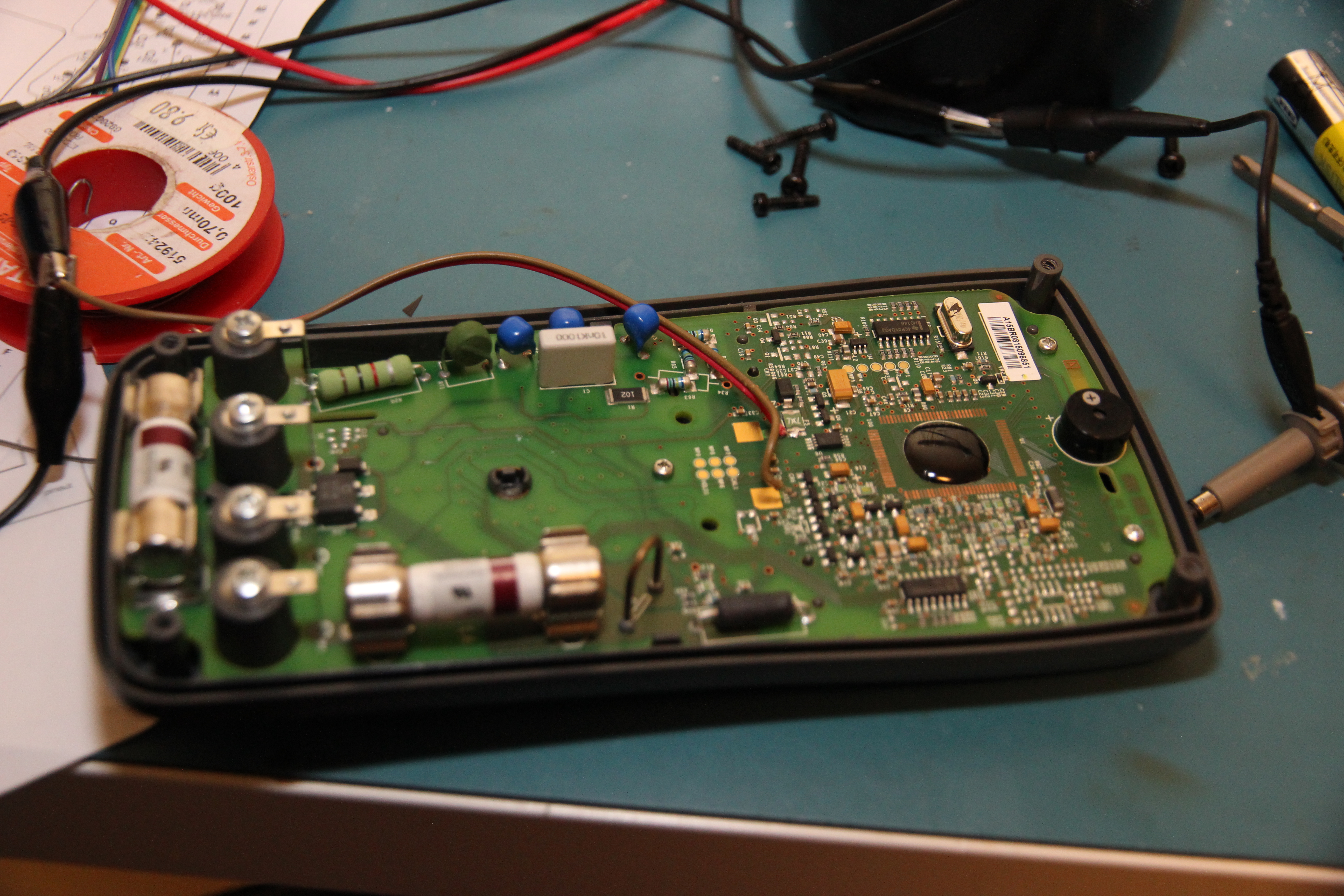
So, first course of action is to open up the multimeter. Unscrewing the four screws in the corners,
plus the two in the battery compartment, shows the back of the PCB. It is very neatly laid out, with
enough input protection with isolation slots, a bunch of resistors, PTCs and two huge HRC fuses, all
in order to minize the risk of injury if you happen to do something stupid while in the neighbourhood
of lethal voltages and/or amps.
At the top of the PCB is the controller. Where the earlier 15B multimeters had a nice LQFP package, making reverse engineering the protocol as easy as reading the type number and looking up the datasheet, I had no such luck: the main chip was a COB, in other words a bit of silicon directly bonded to the PCB and some epoxy on top to protect it. No way to figure out the typenumber from that, except for maybe using acid to get off the epoxy and looking for typenumbers on the bare die. Or is there?
While the chip itself may be a COB, the footprint for the LQFP variant still exists on the PCB as well.
It's also
well-known that the earlier 15B multimeter had a Fortune Semiconductor FS9721-LP3 chip as its brains.
Maybe Fluke got the chip for their new multimeter from the same manufacturer? The manufacturer doesn't
make that many chips, so I got to work downloading the datasheets for all of them and comparing the
pinouts to what I saw on the PCB. One chip was a perfect match: the pinout for the
FS98O24
matched perfectly with the components and nets that were hooked up to it in in the multimeter:
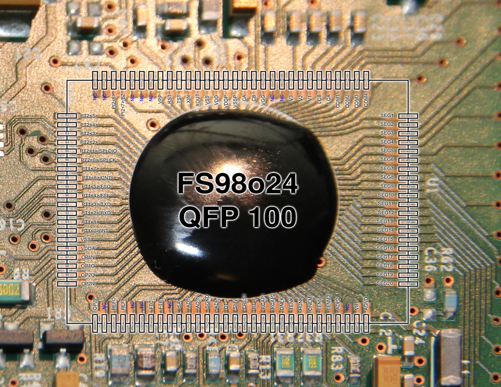
Unfortunately, the FS98O24 isn't a dedicated multimeter chip, where you only need to open up the datasheet and read about the serial protocol. It is an OTP microprocessor which, although geared towards multimeter usage, can be programmed by the system designer to do anything that is needed. I would have to do some more work to figure out a way to get to the data.
One of the interesting things about the Fluke 15B+ is that the PCB has no trim-potmeters whatsoever: there are no analog means for the meter to be calibrated. All the calibration is done digitally, using some pins to connect to the microcontroller. You can actually see where this happens: if you open up the battery compartment, there's a small orange sticker saying 'calibration seal'. If you were to remove this sticker, you'd see six test points on the PCB of the multimeter; in all probability pogo pins in a calibration jig are used to make contact to them.
With the pinout of the main chip known, I could trace out where these pins connected. Two of them were used for ground and power (presumably so the multimeter can be powered from the test jig; with it in place there's no room for batteries), one of them was connected to the HOLD button and the remaining three were connected to the TxD and RxD of the microcontrollers UART, with the RxD for some reason being connected to two pads. The calibration port is a serial port! But how to figure out the protocol?
One of the ways of figuring out an unknown protocol is to just whack data at the port and see how it responds. In this case, we're doing it with an calibration port: it's a given that there are commands that can modify the calibration of the multimeter and throw all measurements out of whack. I didn't want that to happen, so I had to do something against this.
The microprocessor itself is OTP (One Time Programmable) and needs a special interface and a fairly high
programming voltage to do so. Because these pins weren't available on the calibration port, I could be
quite sure that the internal programming at least couldn't be changed by poking random values into the
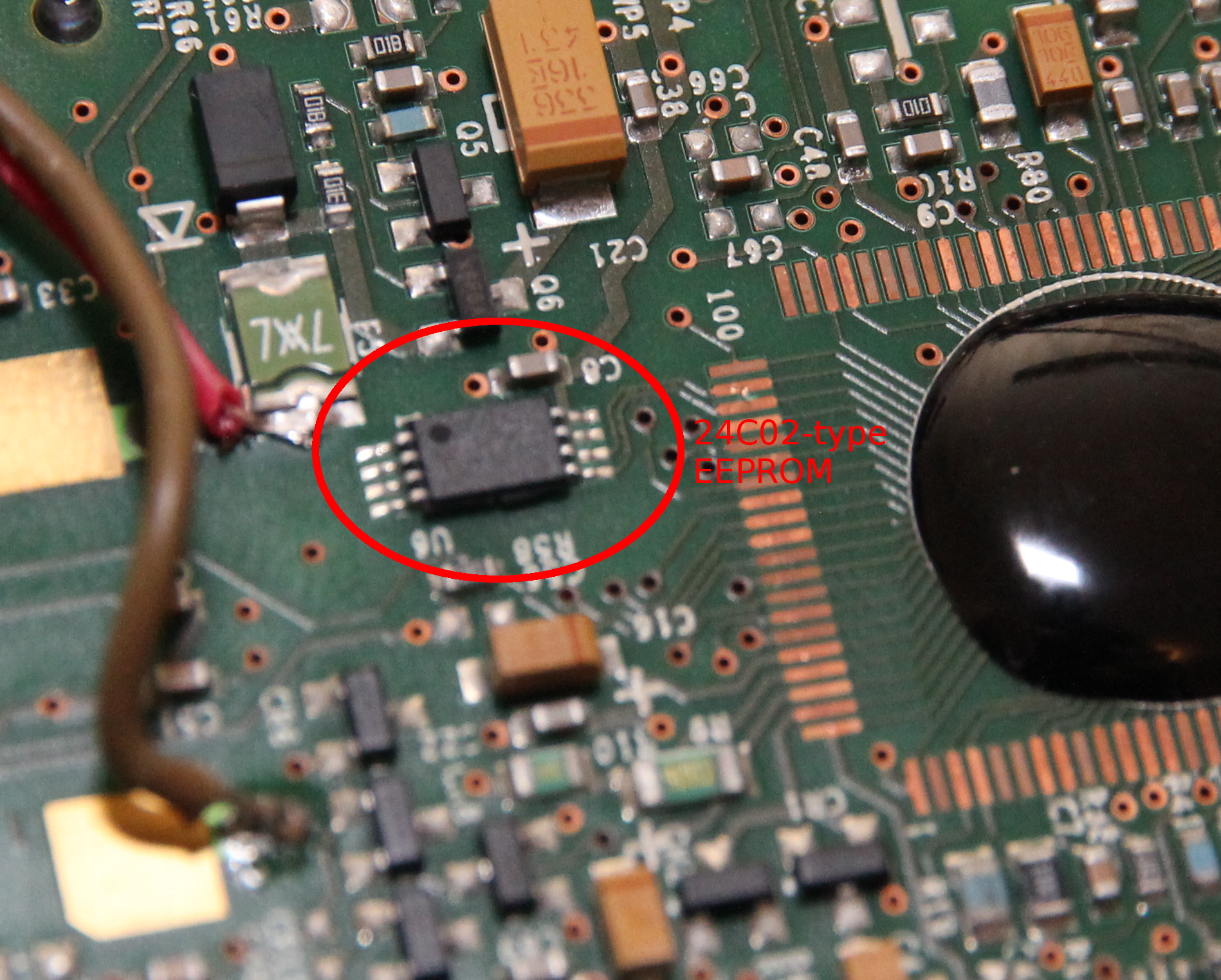
serial port. The microprocessor also doesn't have any EEPROM to store calibration values, and Fluke seems
to have remedied that by connecting a small 8-pin I2C EEPROM to some GPIO pins. In theory, that's the
only place the calibrarion data could be stored, so desoldering the EEPROM should save my precious
calibration from being overwritten. (The EEPROM actually has a write-disable pin which I could ground
to make the calibration data read-only, but because of the layout of the PCB, desoldering the chip was
easier.)
With the EEPROM removed, the multimeter wasn't really a happy camper: it booted up with an error and all the values were off. But it still worked up to a degree; enough to try to wiggle the serial port. I connected one of my trusty 3.3V USB-to-serial converters to the relevant pins. Now what? I didn't know the baudrate or protocol... Maybe just whacking random bits at it at a random baudrate could do something. I connected a scope to the TxD of the multimeter, and on my PC I generated random bytes by doing a
cat /dev/urandom > /dev/ttyUSB0And yes, every now and then the multimeter seemed to react to the barrage of random data with some bytes of its own. It seemed to communicate at 2400 baud. I couldn't figure out the parity and stopbits, but it was safe to assume it would use the same values 99% of serial ports use: 8 databits, 1 stopbit, no parity.

Now on to figuring out the higher level protocol. I again started by sending random bytes, but this time using a small hacked together C program. It would send a byte, then listen for any response and print it out. Using this program, I found out the multimeter would send a response to the byte 0x64, or 'd' in ASCII. The meter would also do some interesting things on other bytes, like simulating a press of the 'hold' button and turning on and off the high-voltage indicator. All these seem to be one-byte commands, but maybe there also are multiple-byte commands?
To check this, I modified my program to send a byte, then the 'd'-byte. If the first byte is part of a multi-byte command, the 'd' would be interpreted as the second byte of this command and I wouldn't get the response the 'd'-command would normally give. Unfortunately, I could find no multi-byte commands this way.
All in all, I had found three commands that changed something on the LCD and one command that returned 8 bytes of data. The meaning of these bytes was pretty easy to guess: most multimeters with a serial output send either an ascii string with the measured value, or a binary string with each bit corresponding to a segment on the LCD. It seems the Fluke firmware does the latter: each bit maps neatly to a LCD segment.