Hardware
Now I had figured out how to read the value on the display of the multimeter, what to do with it? The easies way to use it was to build the usb-to-serial converter I used for my experiments into the multimeter, hooking up a laptop if I wanted to log something. This is an awful solution, though: it breaks the electric safety of the meter by connecting its ground with the laptops ground as well as requiring me to hack a hole into the meters exterior. A wireless transfer method would be better, being both galvanically isolated as well as not requiring any ugly holes.
I decided to put in one of the ubiquitous Espressif ESP8266 WiFi modules: by now I'm very familiar with them and they are more than capable of giving the multimeter some connectivity.
Unfortunately, the ESP8266 is a fairly power-consuming chip if you compare it to the multimeter chipset
itself: while the multimeter itself uses about 1.5mA, the ESP8266 adds a few tens of mA to this when active. WiFi
isn't always needed either; that is why I devised a schematic to allow powering it on only when needed.
Some hints about reading this schematic: there are some connections between the analog bit in the top and the ESP,
and they're named ESP_xxx. There are also some connections to the internals of the multimeter, indicated
as (component-indicator, pin); these refer to components and their pins on the PCB of the 15B+.
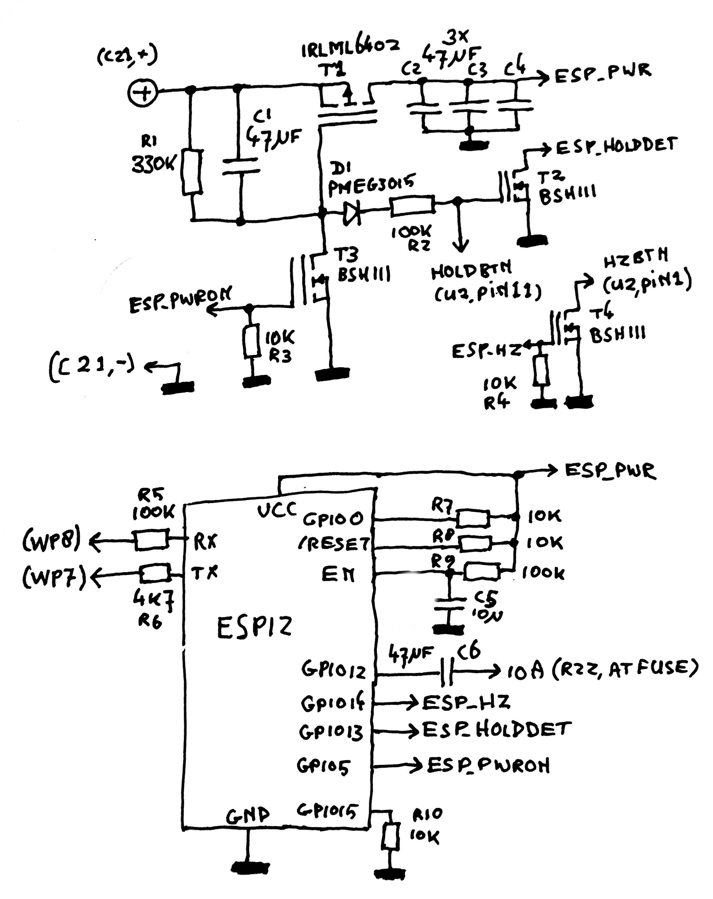
The nice thing about this schematic is that it hooks into the HOLD button. Normally, you would press this once to stop the display from updating and press it again to continue measuring things. With this schematic, if you hold the button for more than 3 seconds, it will turn on the WiFi module.
The way this works is as follows. The power of the entire schematic is connected to a tantalum capacitor called 'C21' on the meters main board. This capacitor carries the battery voltage when the meter is switched on only, so when the meter is off, there's no chance of my add-on consuming any power. Normally, when power appears, the mosfet T1 will not conduct and the ESP12 module is powered off; because of this, all it's GPIO lines are low and none of the other mosfets will conduct either. The multimeter will work happily in non-WiFi-connected mode. Now, when HOLD button is pressed, the button will pull down the HOLDBTN line and C1 will slowly charge through D1 and R2. When the HOLD button is released pretty quickly, nothing more will happen and C1 will be discharged again through R1. When, however, the HOLD button is pressed long enough for the voltage over C1 to rise above the gate threshold voltage of T1, T1 will conduct and start powering the ESP12 module. The firmware loaded into the ESP12 will then make ESP_PWRON high, which makes T3 pull down the gate of T1, making sure the ESP12 will keep getting power even if the HOLD button is released. When this inevitably happens, D1 makes sure the voltage on the HOLDBTN line can actually go high again instead of it being grounded through T3.
The rest of the schematics are mostly glue components plus some extra mosfets to interact with the buttons. T2 is used to detect the state of the HOLD button after the ESP8266 is powered on; I use this functionality to reset the ESP12 back into AP mode if I ever need to connect it to another access point. T4 allows the ESP8266 to ground the pad that leads to the 'Hz/%' button on the ESP17B+ equivalent of this multimeter. The ESP12E+/15B+/17B+/18B+ actually seem to be based on exactly the same PCB and processor/firmware, and a fair amount of differentiation seems to be done by just leaving off buttons for some features. In this case, the 'Hz/%' functionality on the 15B+ seems to be entirely functional, Fluke just left off the physical button. With this mosfet, I can still change the multimeter in Hz/duty cycle mode, without having to modify the exterior of the meter. (The same thing is true for the min/max functionality: it too is only missing a button, but because I intended to add graphing functionality anyway, I didn't bother connecting that.)
Finally, there's R9/C5, an R/C network to reset the ESP8266 on power-up (needed because its supply voltage raises fairly slowly) and R5/R6 connecting the serial port of the ESP8266 to that of the multimeter. GPIO12 is also connected to the 10A input of the multimeter using a 47uF capacitor so the ESP8266, so it can couple in some signals there. The purpose of that will become clear later on.
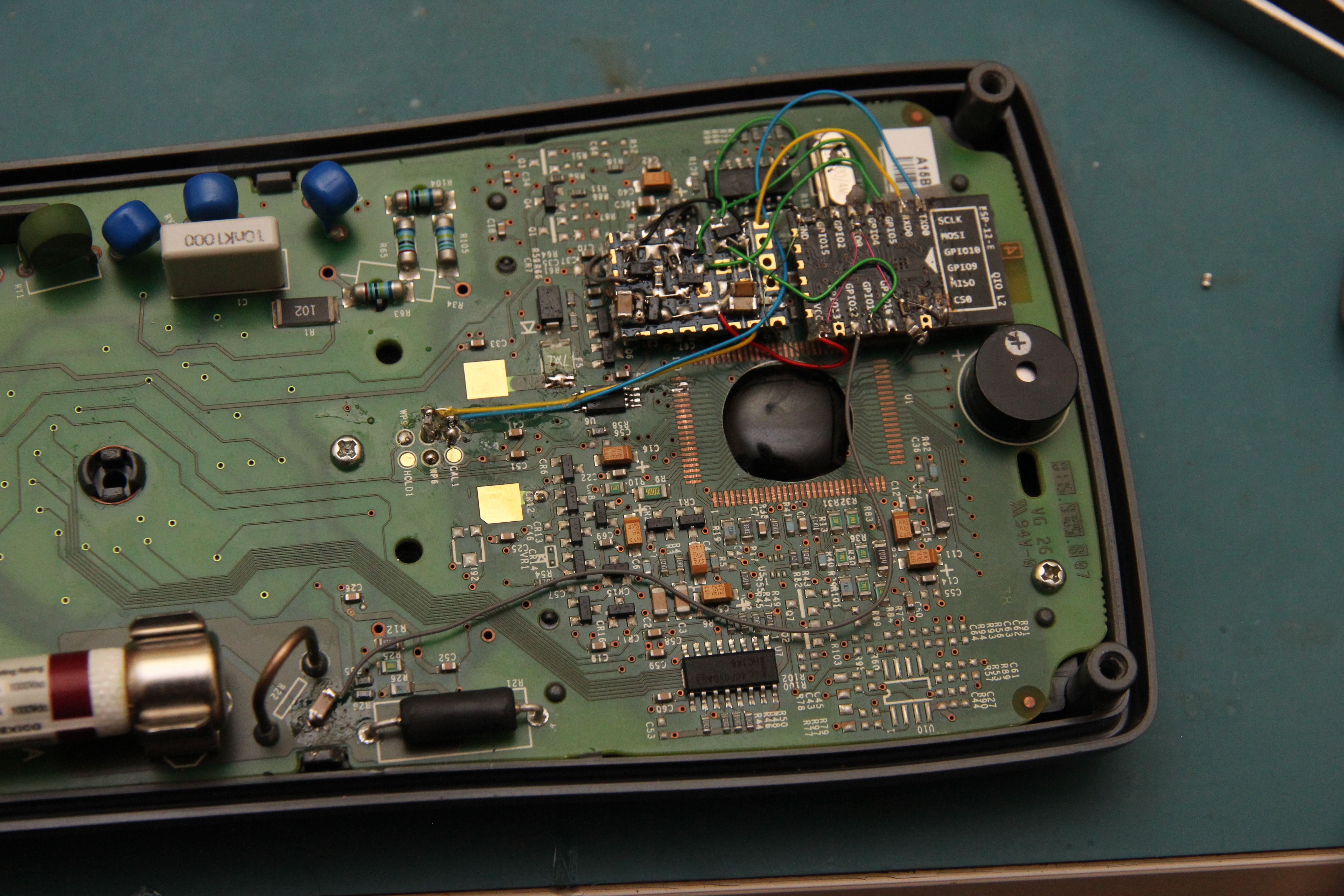
I decided to build the schematic up on a small PCB that could sit over C21 on the meters main board,
sipping power from there. The ESP12 is mounted using double-sided foam tape to the PCB as well. It's
not the nicest solution ever, but it should be sturdy enough.