Software
A WiFi-module alone does not make for a servicable WiFi multimeter, there's also a software side to that. For that, I used my trusty old esphttpd library/framework. It allows me to serve up a website which has the needed html and javascript to make a nice user interface for the multimeter, websocket support to get the measurements to the browser and a nice interface to connect the thing to a WiFi access point. It also allows over-the-air firmware upgrades, allowing me to push bugfixes or new features to the multimeter from my webbrowser or the command line.
The most time-consuming bit in developing the software probably was the interface to the multimeter: while something that spits out the command to read out the LCD was pretty easy to make, it cost a fair amount of time to figure out which bit in the reply corresponded to which LCD segment. In the end, however, I managed to write a routine that entirely decodes all segments on my LCD into a value and an unit.
For the user interface, I had the webserver serve up a simple HTML page with some Javascript and
a copy of Chart.js. The Javascript uses a websocket to connect
back to the webserver; the webserver will serve up the measurements taken from the multimeter
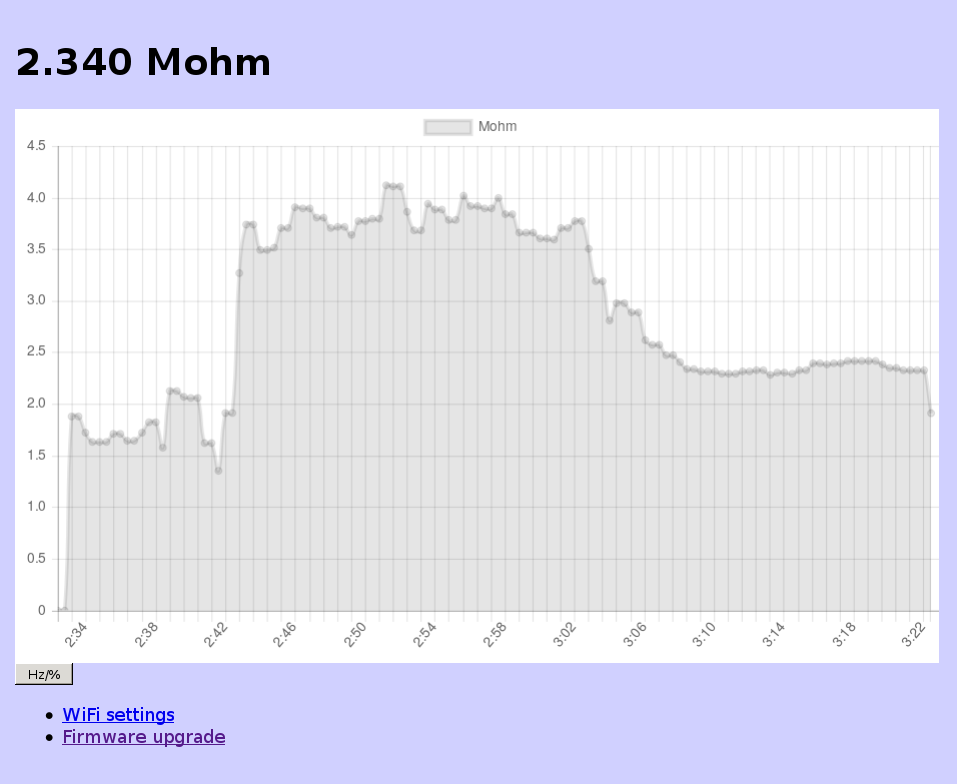
periodically over that websocket, and the Javascript bit displays that in the page. It will
also feed the data to Chart.js, which will dynamically update a line chart so you are able to see
trends.
Although you can leave open a webbrowser and take a screenshot of the line chart when you're done, in practice this isn't the most precise or reliable way. For that, the multimeter also listens on a TCP port; connect to that and you'll also see the measurements come in over that, ready to be written to disk or processed directly using a script or program.
There was still one thing I did not like, and that was the fact that when I want to measure something, I just want to turn on my multimeter, switch on WiFi and use my laptop to connect to it. For that, it's useful to know the IP of the device. Obviously, I could SSH to my server and search through the logs to figure that out, but that would be a pain in the ass to do every time. I decided to see if I could make the multimeter itself display its IP.
Unfortunately, there does not seem to be a command for sending things to the LCD. I even tried reading out the firmware over a secondary set of testpads that were connected to the programming interface of the main controller chip of the multimeter, but the programming protocol is not documented by Fortune Semiconductors, and at least without the 12V power source needed for actually programming the OTP applied, my routine of sending random data to the pins did not give any result. Maybe the programming port is only enabled when the 12V is there, but I did not try that out of fear of accidentally overwriting bits in the OTP memory, bricking my multimeter.
At that point, I decided on another approach. I soldered a GPIO via a 47uF capacitor to the 10A input. Normally this GPIO is in high-impedance mode, and because of the low impedance of the shunt used to measure 10A, it will change nothing in the measurements the multimeter takes. If, however, the ESP8266 detects it is started with the multimeter in 10A mode, it will switch the multimeter into duty cycle measuring mode and output the digits of its IP encoded in the duty cycle of the signal it will output on the GPIO pin.
In case the access point the ESP8266 wants to connect to is unavailable, this will give no usable IP. In that case, by pressing the HOLD button for five seconds, the multimeter switches into access point mode. This allows connecting a phone or laptop directly to it in order to read measurements that way, or to configure a different access point.