Modifying the hardware
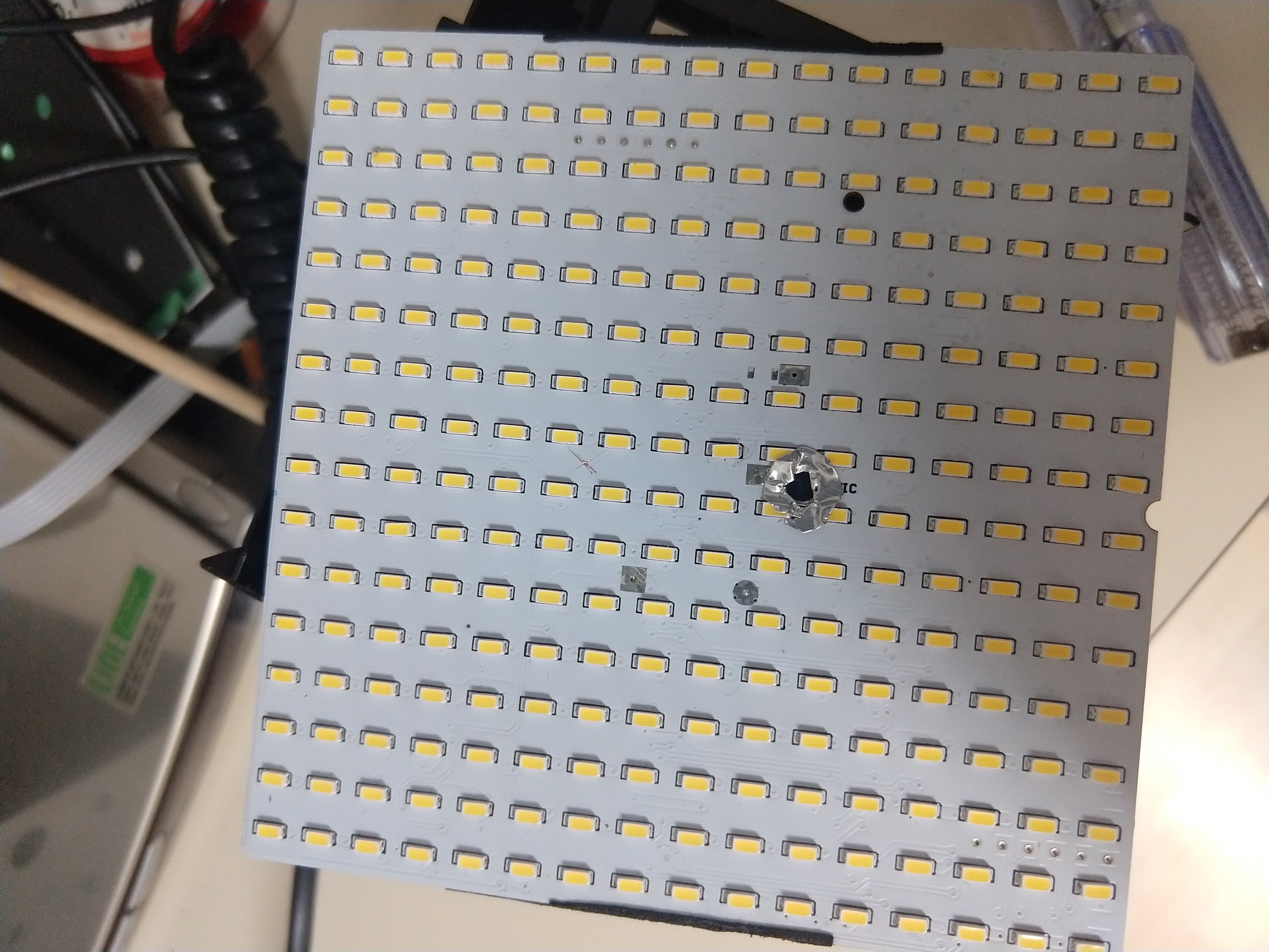
My idea was that I could perhaps replace the hardware with an ESP-Cam. This is a very cheap (EUR10 or thereabouts) board that contains an ESP32 WiFi/BT chip, a few megabytes of PSRAM as well as a camera module. The idea was that as I am not that interested in disco lights, I wanted the box to react to something visual. As there already was a hole in the front of the hole for the camera, I imagined I could re-purpose this for the camera. I'd also need to drill a hole in the white PCB carrying the LEDs where the microphone was; luckily, aside from the now-useless microphone traces, there would be only a single LED trace that this would break. I drilled the hole and fixed the trace. Temporarily tacking the original PCB back in place and turning the cube on confirmed that the LEDs still were all working.
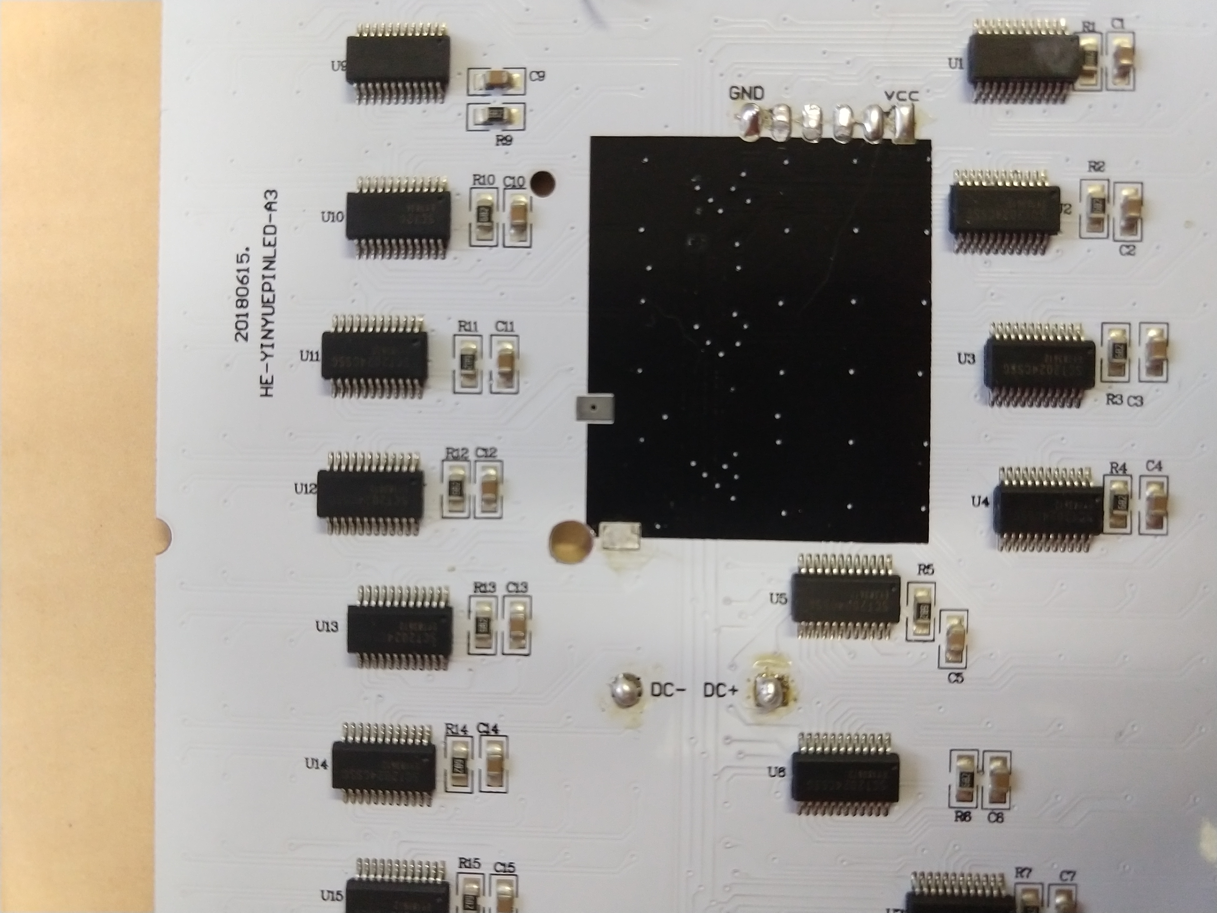
Now I had a PCB with a hole in it, and all that remained was to hook up and mechanically connect the ESP-Cam. The designers were nice enough to mark the purpose of all solder pads on the silkscreen of the green PCB, so there was very little guesswork involved. As the power supply is only 4V, I connected it directly to the 3.3V input of the ESP-CAM. I had to do this, as when I applied it onto the 5V Vin pin instead, it didn't want to boot... most likely the LDO had a dropout that was a bit too high. Looking back, it probably would have been better to put a diode in series with the 4V supply, so I would end up at 3.3-3.4V, but this solution works as well; the ESP32 is a fairly hardy beast.
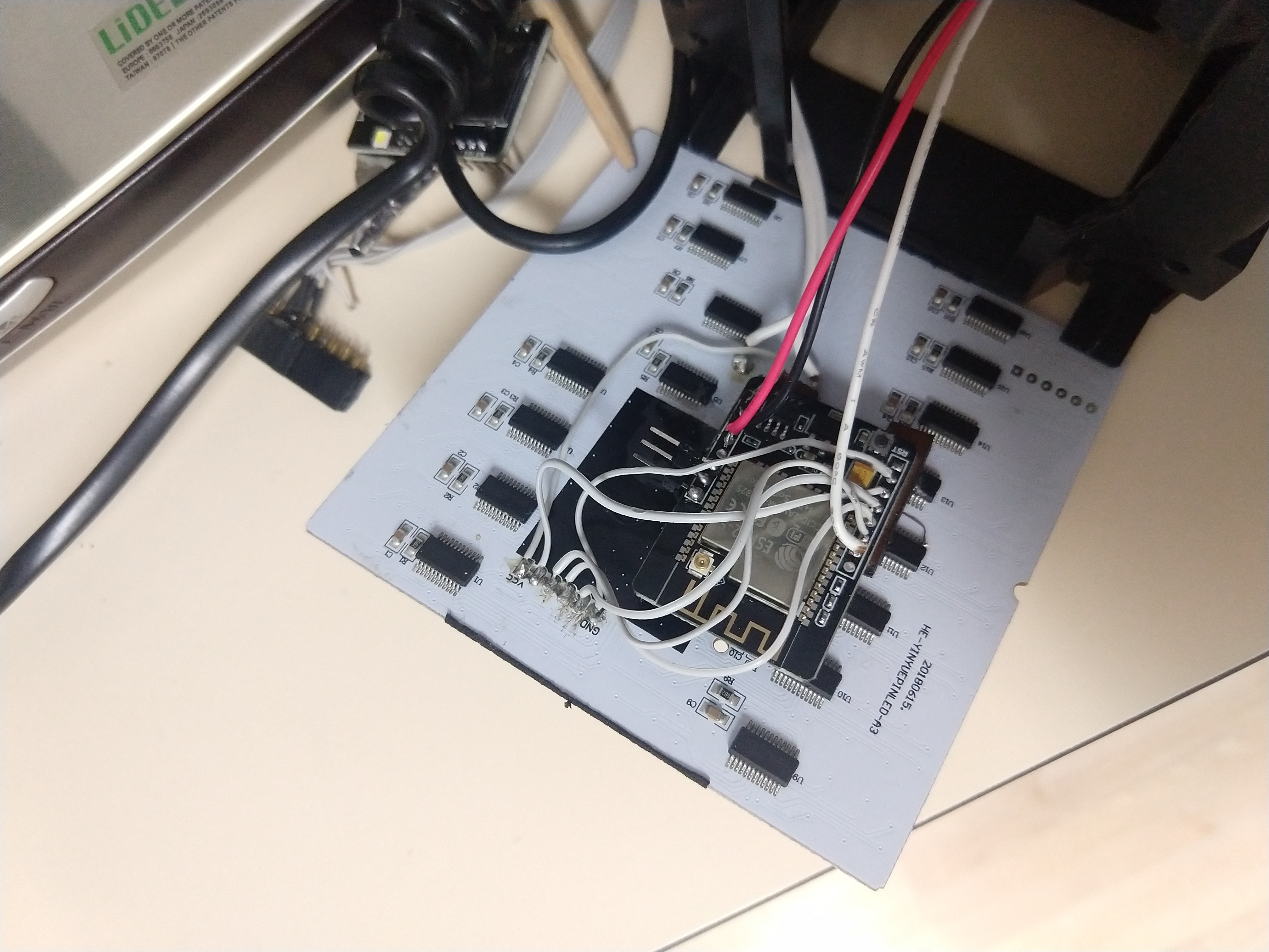
After soldering the connections in place, I still had the mechanics to sort out. As this was a quick and dirty project and I already had desoldered the headers from the ESP-Cam earlier, I could get away by using a few spacers and a large helping of epoxy to make sure the camera would keep its alignment with the hole.
After this operation, I had a remaining issue: the LEDs next to the camera were shining into the aperture, generating all kind of weird artifacts. The first step to stop that to was to cut a little bezel out of aluminium tape and use that to shield the camera from direct light.

The second step was using acrylic paint. This is the plastic insert that contains all the diffusers the LEDs shine through. I already enlarged the hole it had for the microphone to give the camera a wider aperture, but that lead to the issue that the hole was too obvious and still shone lots of stray light on the camera. A dash of black acrylic paint fixed both reasonably well; the camera could still pick up a fair amount of light from the LEDs but now would not be entirely swamped by them anymore.
Now the brain transplant was done and the box was ready to put together again, I could begin on the software side of things.