Software
On to the software. First order of business was to get the LED drivers under control. That is not hard; the LED driver signals almost directly map to the SPI peripheral inside the ESP32: the CLK pad on the PCB goes to the CLK of the SPI peripheral, the DA pad on the PCB goes to the MOSI of the SPI signal. This will allow 256 bits to be clocked into the LED driver chain: each bit that is clocked in controls if the corresponding LED will be on or off. Aside from that, there's also the LAK input. If this is low, the LEDs will keep their previous value, regardless of what is clocked into the shift registers; if this signal is made high, they will all at the same time switch over to the values that are in the shift register at that point. Finally, there is an EN input that enables or disables all the LEDs; while I did connected this to a GPIO, I just enable the LEDs all the time in software.
From this, I could obviously turn the individual LEDs on and off and have a black-and-white display. However, this is not what I wanted. With enough processing power, the display should be capable of doing grayscales as well; this just requires turning the LEDs off and on faster than the eye can see. To do this for one LED, you'd usually use PWM, but for 256 LEDs that would take up a fair amount of the ESP32s CPU power. Instead, I decided to go for Binary Code Modulation (also called Bit Angle Modulation) which is a technique to get grayscale that requires less CPU power. I already successfully used this in other projects as well, so I was pretty certain it would work.
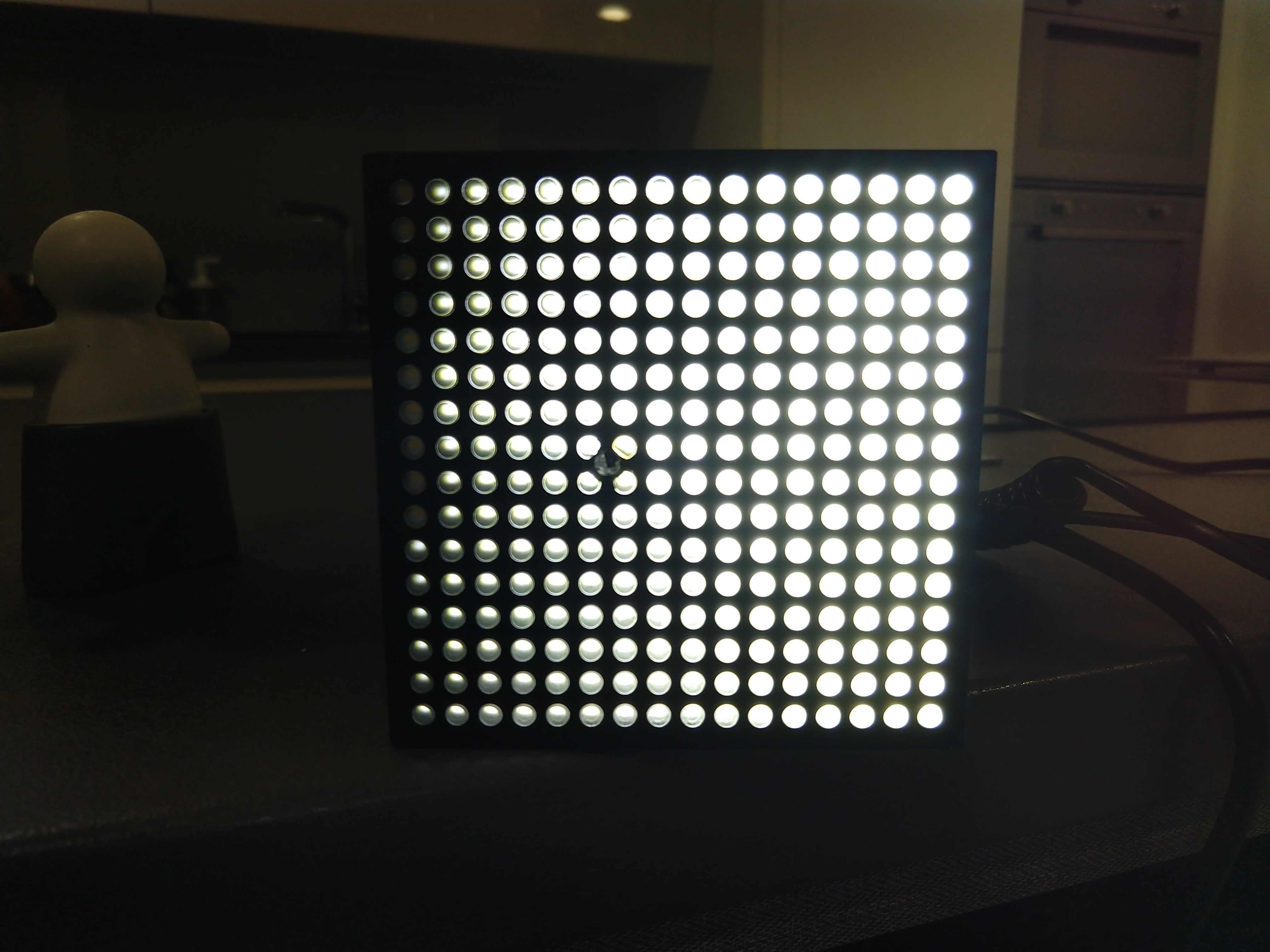
And work it did. I also added a lookup table for CIE lightness to PWM table, as the eye effectively has a non-linear response to LED intensity; the lookup table corrects for this. All in all, I could get a fair amount of grays, with optical intensity linearly scaling with the pixel value I set.
Getting the camera bit to work wasn't that hard: there's an ESP-IDF component you can plunk into your project and it takes care of all the camera communication and setup: you just set up the specs you want and can then request it to return a bitmap of what it currently sees. The only thing I could not quite use out of the box was the fact that auto-gain and auto-exposure were enabled by default, and these interfered quite badly with the way the LEDs were controlled: depending on where in the Binary Code Modulation sequence the image was taken, the camera would increase or decrease gain an exposure pretty abuptly. This was fixed by putting the camera in manual gain and exposure mode and manually having the code look at the image to see if these parameters need compensation. By doing it manually, I could also exclude the pixels I knew were looking directly at the LEDs, so those could be taken out of the equation immediately, which also helped a great deal in getting a stable image.
Now I had a camera and an 16x16 grayscale canvas; what to do with these? A thought came to me: back in the days of the very first Macintosh computers, there was a popular extension that would do nothing but put a pair of cartoon eyes in your menu bar. Those eyes would do nothing but follow the cursor around. (A variation on this theme for Linux/Unix still exists under the name of 'xeyes'.) What if I could make this in real life?
To start, I needed some images of eyes. As I didn't see myself as being able to draw anything that would be worth displaying, I decided to use my own eyes as the base imagery instead; I took a quick video of me looking and blinking in all directions. Note that due to the situation I had very little in the way of professional tools: this is me laying on the ground to maximize the light coming from the overhead fluorescent bulbs to get the most recognizable image I can; the entire thing was filmed on a handheld smartphone.
As the source data was somewhat crappy; a fair bit of work went into postprocessing. I started by cropping out the bit that roughly was around my right eye. I then converted every frame of the movie I made into an image and removed all images that were superfluous; in the end, I mostly had good specimen of me looking in a certain direction and a few of me blinking. However, because I used a handheld mobile phone to record myself, the video was a bit shakey and the images weren't aligned. To fix that, I ran Hugin, an image stitching program which is normally used for panoramas and HDR imagery, over the image set; this output a bunch of images perfectly centered on that bit of my face. Now all I needed to do was to mark in which direction I was looking and if I was blinking. This was done by first converting all images to grayscale and then loading them up in Gimp. For each image, I used a red dot to indicate where the center of my pupil was, plus a red dot in either the left or right corner to indicate if I was blinking, and if so if my eye was half-open or closed.
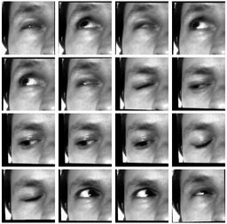
With every image marked as such, it became very easy to use some scripting to get the location of the pupil as well as the blink status. The script also scaled the images back to 16x16 pixels and saved it as a raw binary, ready for inclusion in the firmware for the ESP-CAM module. The end result was a set of images plus an index of where the pupil was and how far mid-blink, if any, it was.
The ESP-Cam has a fairly simple to use camera library component for ESP-IDF, so getting images out of it wasn't too hard. I set it to capture 120x160 grayscale images, as those were the easiest to process and I didn't really need any more resolution, given the end result was going to show up on an 16x16 screen. However, I did still have a hardware issue to resolve: the camera still was very close to the LEDs.

A first attempt to solve this is by calibration: as the device starts up, it'll take two pictures: one with the LEDs close to the camera lens on and one with only the LEDs far away from the camera on. By subtracting the two, it becomes obvious which pixels are influenced by the LEDs. These pixels get stored in a mask; the pixels marked in the mask are ignored later on. The image above shows those two pictures as well as the mask.
With a now more clean image, I could move on to the movement detection. This was achieved by taking a frame from the camera and subtracting the previous frame from it. I then could figure out the amount of movement by adding all resulting pixels. I could then calculate where the movement was concentrated by takin the average of all pixel coordinates weighted by the frame difference at that pixel. Finally, there is some filtering magic going on to make sure the box does't look around like a Jack Russel with ADHD: something needs either move consistently or a fair bit before it attracts attention.
The only problem left was that when it was very dark, the motion detecting algorithm would sometimes trigger on the reflection of the LEDs in shiny objects that happened to be in the room: if the eye blinked, it would then be attracted to its own reflection. As this is not quite what I wanted, I got around it by making the motion detection algorithm 'blind' when the image on the LEDs changed; this effectively stopped the behaviour. It makes it a bit more realistic as well: you can't see while you're blinking, after all.
The firmware has a few debugging modes that show the entire process. Here's a little video illustrating it: