Hard/software
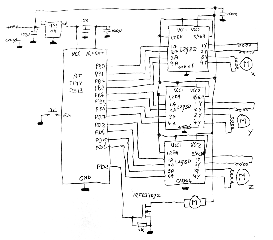
For hardware, I thought I could get away with a small AVR, some stepper motors
drivers and a transistor to drive the tray motor. I picked some L293D chips as a
stepper driver, a random N-channel mosfet for the tray motor and an ATTiny2313 to
drive it all. The schematic is pretty basic:
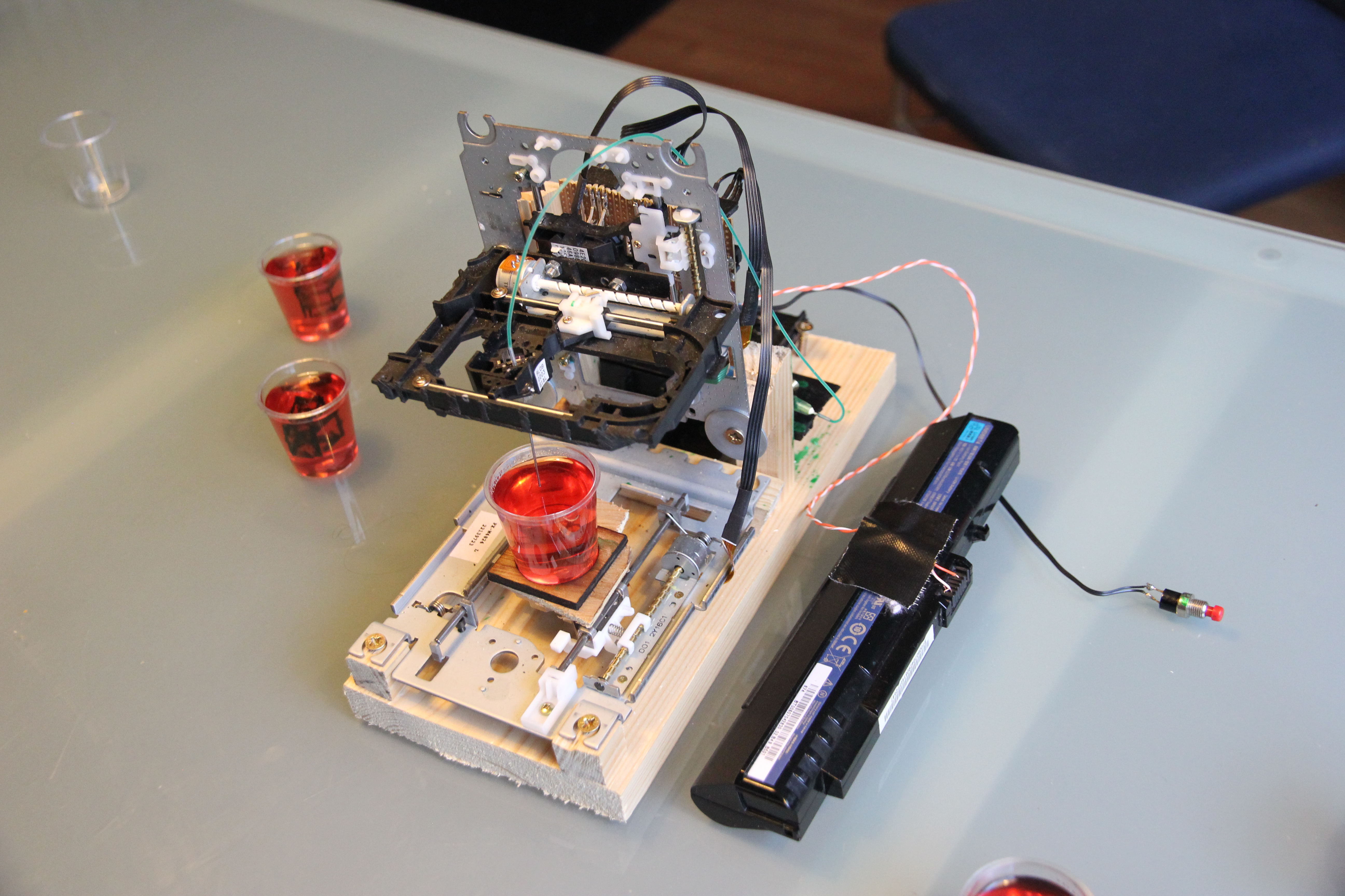
At first, I wanted the 3d-printer to accept figures from an attached laptop. Unfortunately, I never got around to writing the serial port code and in hindsight it may not have been a good idea to bring my laptop to a party where I'd be drinking too. I got around it by hardcoding the coordinates of a few figures into the AVRs flash memory. Now, when you press the button, the AVR will take the next figure and use the L293D H-bridge chips to control the steppers to 'paint' this picture in the jello. When a line needs to be drawn, the AVR will also use the mosfet to turn on the DC-motor, making the syringe dispose the food colouring into the jello.
If you've ever worked with steppers driving something linear, you probably notice I'm missing something pretty basic. With stepper motors, you do know precisely where you're going, but the linear position of the actuator it's connected to (aka the position of the needle) isn't known. Normally, a device would have end switches so it can detect if the carriage can't go any further. On startup, it'll run the carriage into that switch so it knows exactly where it is. With my setup missing that switch, how does it know where the carriage is? Basically by doing the same thing: it'll run the carriage into the end stop for a good while. If the carriage reaches its limit, it'll slip back and stay there. This gives quite some wear-and-tear on the mechanics and isn't the most elegant solution by a long shot, but for a device that isn't used much and with me not having enough GPIOs left to hook up switches, it had to do.
The software is pretty simple: it has to be to fit in the 2K of the controller I chose, but even then, it's still fairly advanced. The stepper motors are controlled using micro-stepping: Steppers like this have at max only 8 angles you can put them in by just sending DC through the coils. The firmware improves on this meager resolution by doing a sort-of PWM between two of the main angles: you can make the motor turn to eg. 15 degrees by telling it to go to 0 degrees for two milliseconds, then then telling it to go to 45 degrees for one millisecond and repeating that. Apart from that, there's also a PWM going on to switch the motors off and on: the motors aren't supposed to run on 10V but more likely are made to accept 5V, but by turning them off half of the time, I get to save money and soldering time on extra voltage regulators. Yes, it's a hack, but good enough for a party.
The rest of the program basically consists of a bunch of coordinates for the figures, and some logic to move the needle point around. Again, all this is written for efficiency but has some drawbacks resulting from that. For example, the routine to move in a straight line uses 16bit fixed-point values with only 3 bits behind the decimal point, meaning quite some inprecision in the angles the lines can draw. Again, I didn't care: no one is going to pull out a ruler to measure the correctness of a line in a jello shot. If you want to re-use the code, I'd suggest expanding that storage a bit for more precision.
With all that done, all I needed was a power supply. I chose the voltage this thing worked at at about
10V so I could power it using a laptop battery. That makes it all pretty portable: