Electronics
The schematic, drawn in the usual Pencil-Paper-And-A-Scanner-Cad (tm):
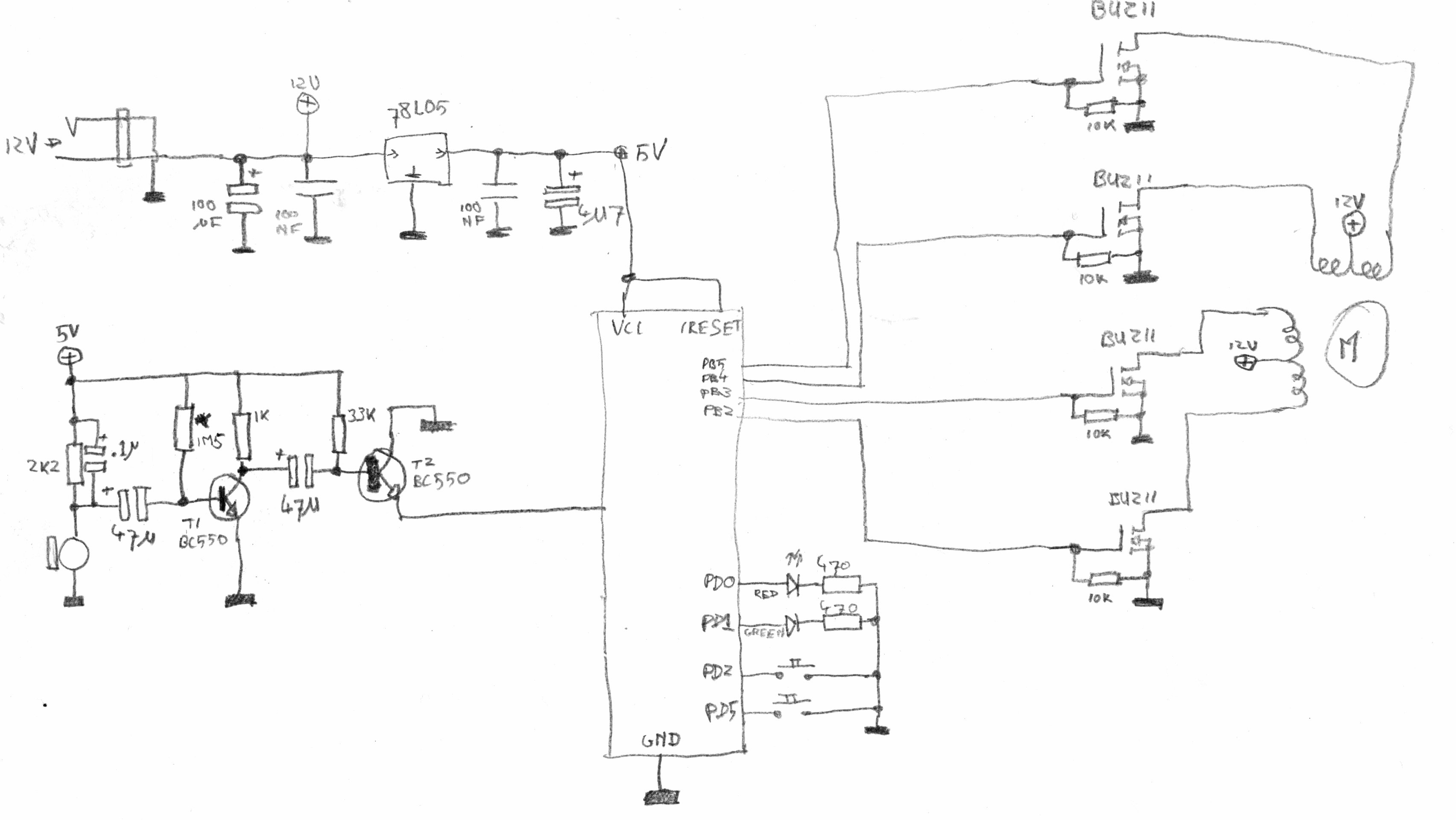
At the top, you can see the power supply. The complete device gets its power
from a laptop PSU. The power-supply is riddled with capacitors: we're switching
coils here, so there will be lots of EMF introduced on the power-supply-lines
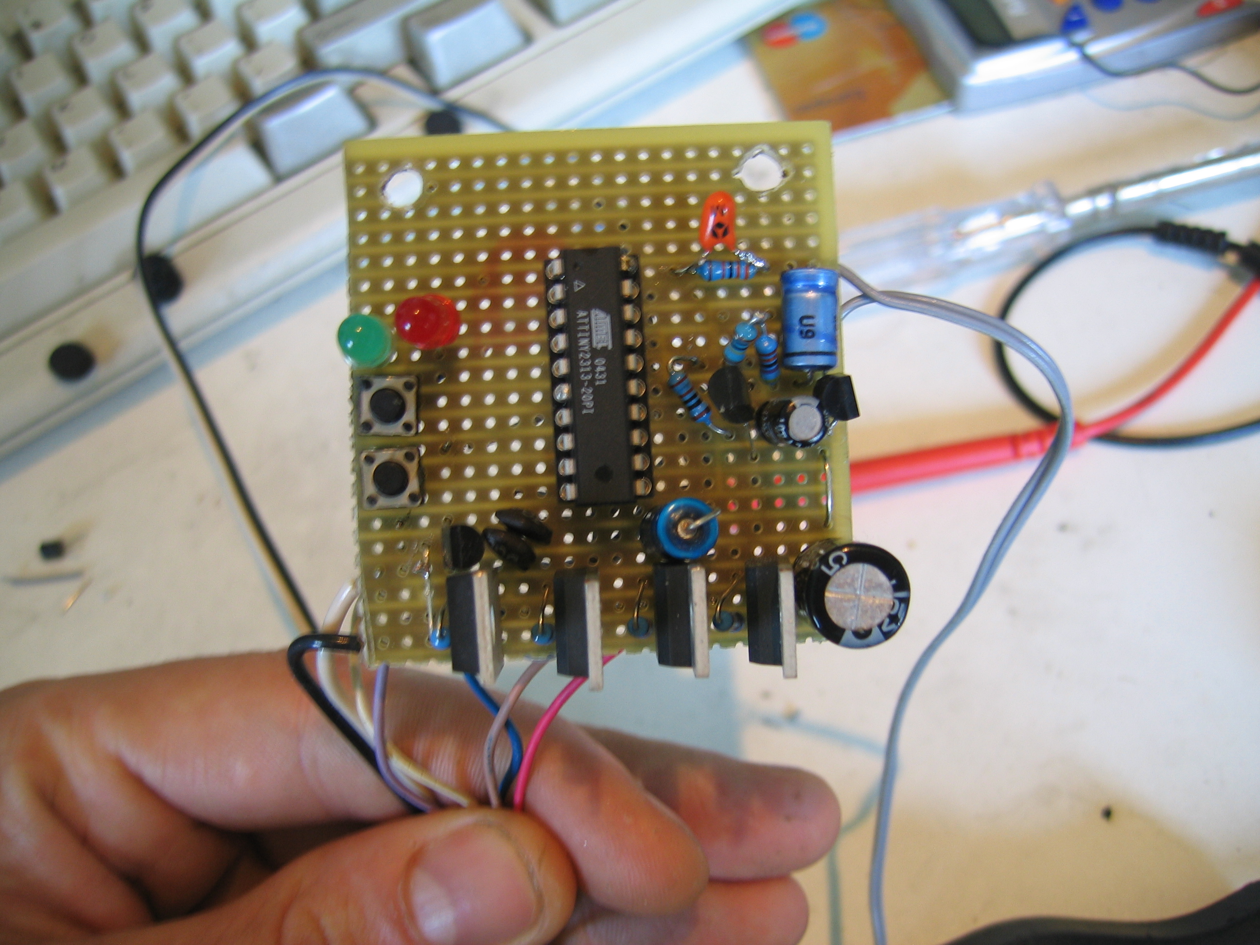
and we don't want that messing with our CPU. In the middle, the brains of the
thing: an ATTiny2313. The ATTiny drives four BUZ11 MOSFETs, who in turn
switch the bipolar stepper motor which turns the knob. While not drawn, the
BUZ11s have integrated ESD-protection diodes to protect form EMF backlash by the
motors coils.
To convince the device to turn its motor, two ways are provided: first of all, a set of buttons for testing purposes. Secondly, there's the analogue stuff right from the microcontroller, which basically is an elektret microphone plus a really crude and hacked pre-amp. It took some fiddling to get the resistor values right, but when I drew the schematic of what I had built, that turned out to be no surprise: as you can see in the schematic, T2 is upside-down, with its collector and emittor switched. When I saw that, I decided to leave it that way: the schematic works OK with these values and the wrongly connected transistor, and I don't feel like re-calibrating the circuit all over again. The amp is a complete hack anyway, btw: I didn't actually feel like calculating anything about it, so I just added resistors and capacitors to the circuit till it did what I needed. There's no logic there, e.g. you'd suspect that the .1uF capacitor would completely filter out any noise the electret cap picks up, but strangely it doesn't.
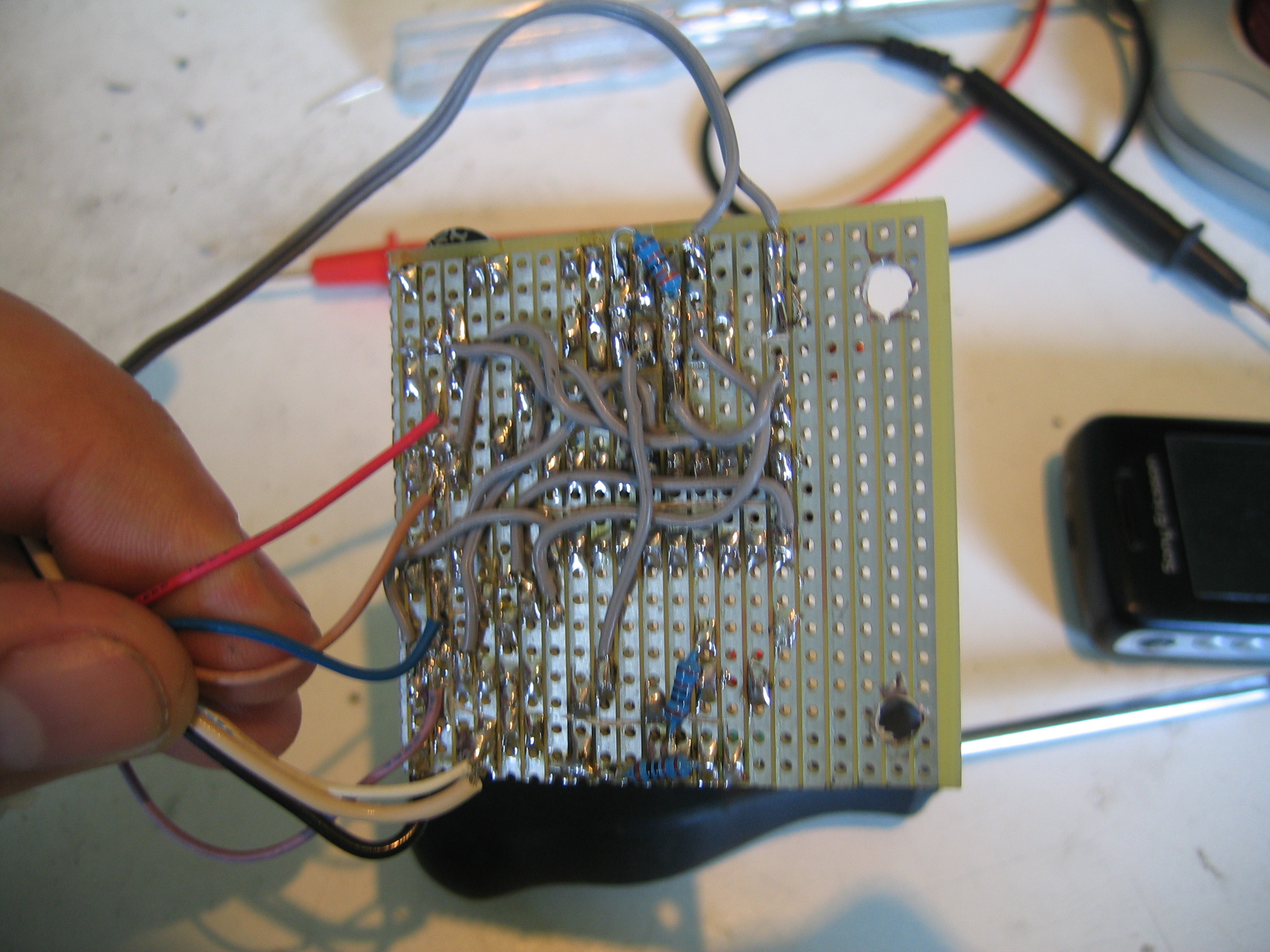
Again, I didn't design a PCB for this, an ordinary piece of prototyping PCB
works just fine: