The Boards
The LED-boards consisted of a double-sided PCB, with on one side the led-modules
and on the other side some logic: a 74hc138 (3-to-8 line decoder), two
74hc244s (buffers) and some MIC5821s (serial shift registers with power outputs).
There were eight power-transistors too, a 5V power-connection and two 8x2 headers.
By carefully looking at the board and using a multimeter, I arrived at the
following block schematic of them:
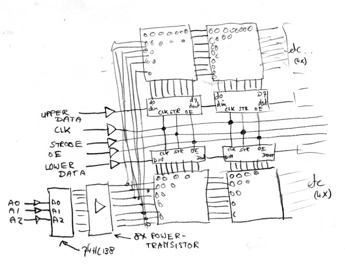
How does this work? Using clk, udata and ldata, we can fill the shift registers with pixel data. As soon as we tickle the strobe of the shift registers and OE is active, the data is displayed on the row of leds selected by the 74HC138/A0-A2.
As you can see, the boards are multiplexed: at every single point in time, only one row of leds (selected by A0, A1, A2) can be lit. The selected row will then display the data contained in the shift registers: if the bit at a certain point is 1, the corresponding led will light, if it's 0 it will stay dark.
With only one row displayed at a time, how can we still display a complete image? We can abuse the fact that the human eye can only see light changes at a certain speed: if we send data and activate every row in order, and we do that quickly enough, the human eye will see it as one static image of data. We will need to do it fairly quick, though: the data for all pixels (called a 'frame') has to be sent at least 50 times a second.