Building it
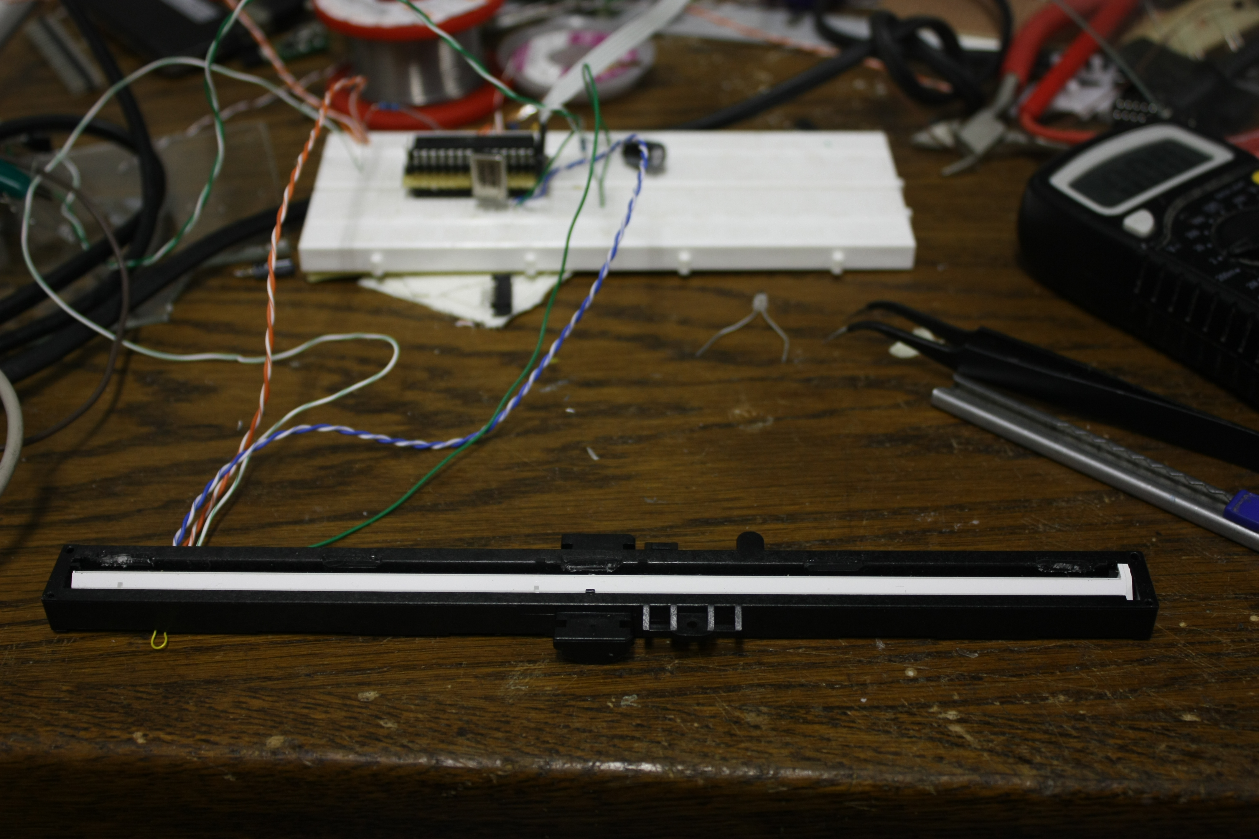
Because the hardware was somewhat experimental, I built it on a small breadboard. The line
CCD was connected to it using the strands from an Ethernet cable.
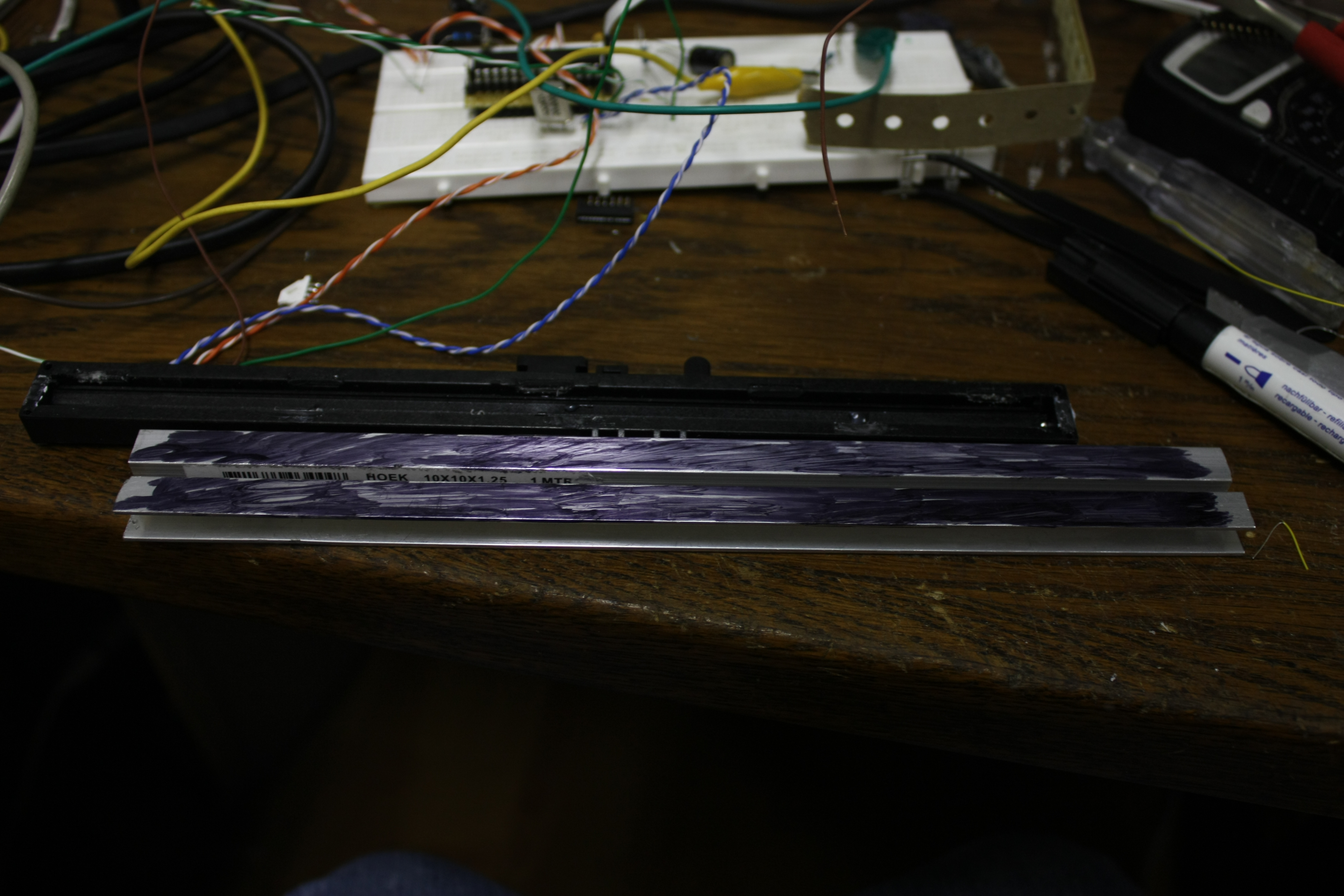
Before getting to work on the rest of the hardware, I had to fix one thing first. In
my experiments, I noticed the sensor would quickly become saturated with the light it
captured from the lamps and windows in the room. I had to make it only look at the
infrared LEDs directly in top of it: I took two pieces of L-profile metal, took
a marker and made two sides black.

I then glued the two pieces on top of the line CCD, with a thin slit left open in between. That
way, the CCD should be affected by ambient light a lot less. Putting an IR-filter in
between should help even more, but I didn't have such a filter and in practice, this
solution is sufficient.
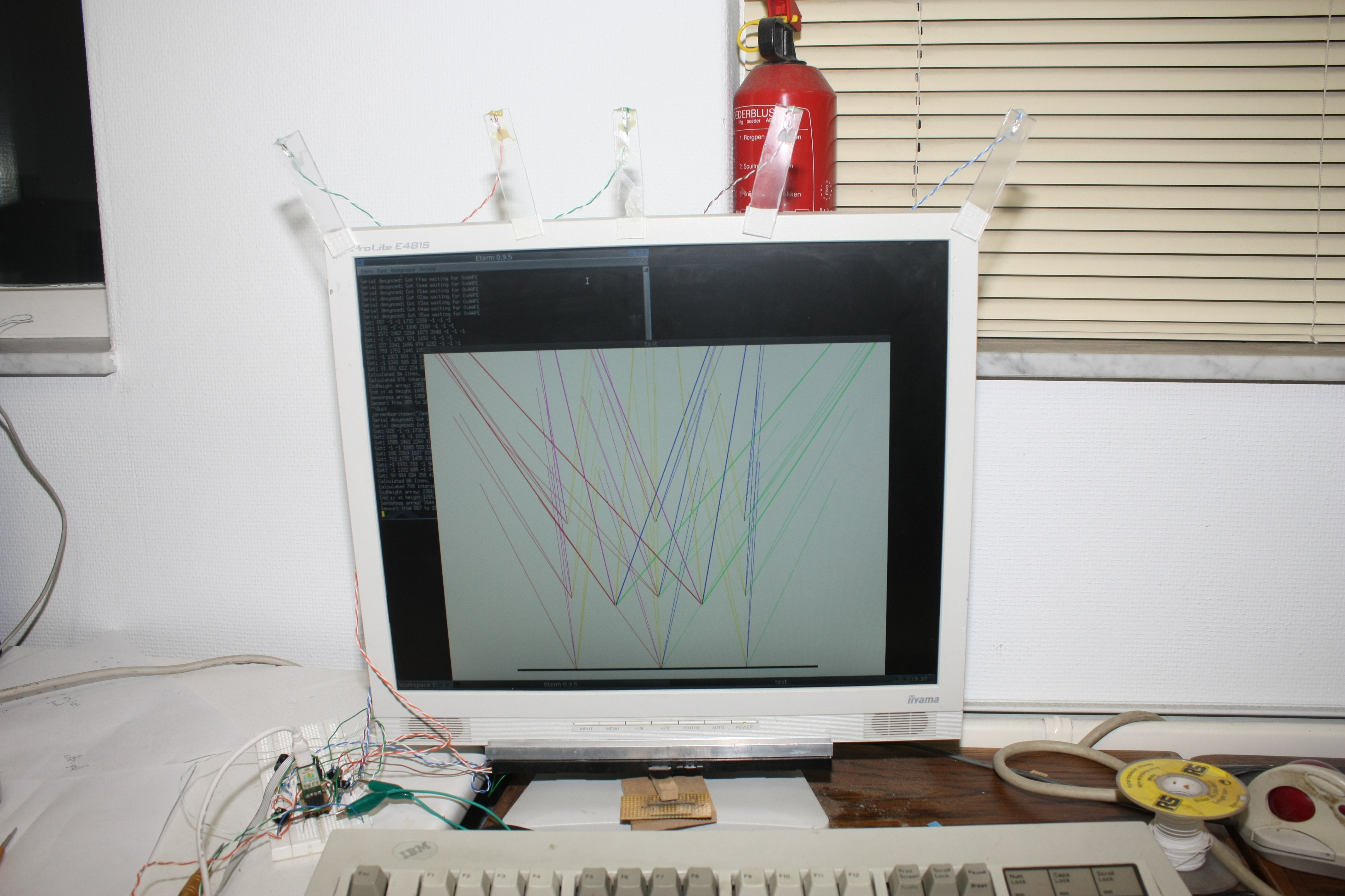
And this is the set-up. Note the infrared LEDs above the screen and the line-CCD
somewhat haphazardly positioned under it.
Another thing you can see in the last image is the end result of something I can't make many pretty pictures of: the PC software. I created a test-app to calibrate the touchscreen and convert the shadow readings of the CCD into positions on the screen. It actually involved a fair bit of trigonometry to get all the formulas right, but the end result works fairly well. What you see in the image is the result of a calibration step: the colored lines all point to where the PC thinks the LEDs are, with a different color for a different LED. The black bar at the bottom indicates the detected position of the CCD. None of these values are hardcoded, all are detected by just touching 9 points on the screen.