More electronics
At this moment, I had the Mac emulation covered (minivmac on the dockstar), the display worked and the mouse and keyboard could be interfaced to the two. What remained? Mostly some small things: the amplifier for the internal mac speaker went down with the mainboard, the power supply had to be connected to the rest of the hardware and I wanted to be able to power on and off the display circuitry and fan when they weren't needed.
First of all: the speaker. Getting audio out of the dockstar was easy: I had enough
USB-ports left and my box of 'misc items' still contained an el-cheapo USB
soundcard. It presented itself as a generic USB sound thingy and got picked up by
the Linux-kernel without problems. Getting the audio to the speaker required an
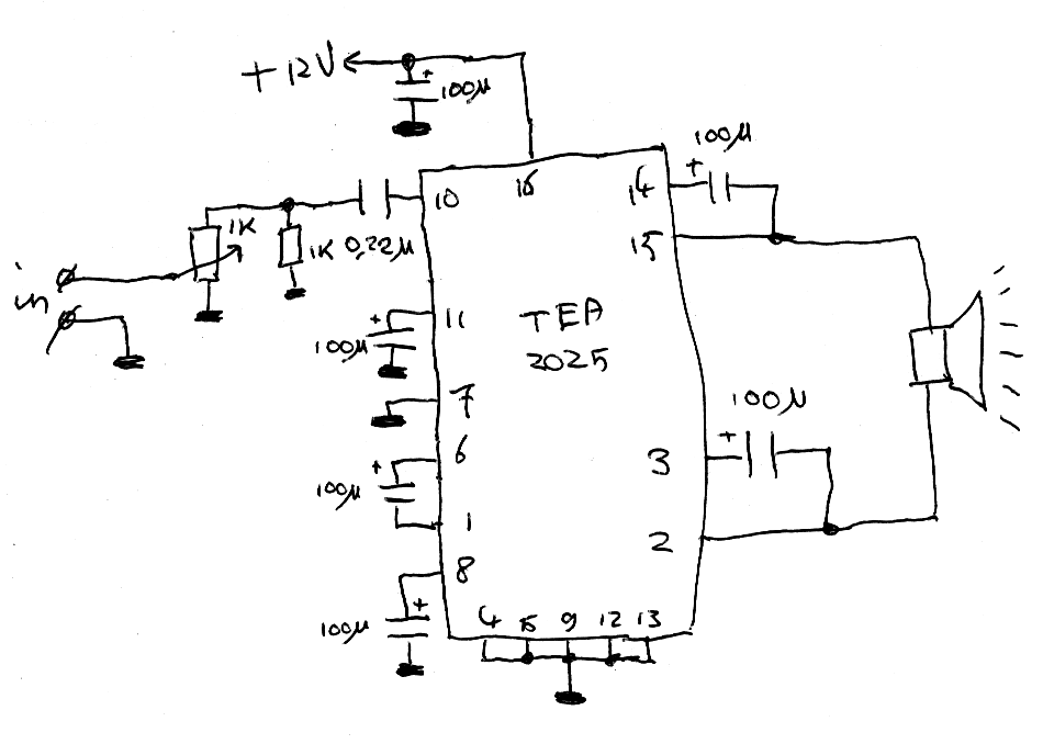
amplifier, though. I didn't have any amplifier ICs around so I just ripped one
off an old soundcard I had: it's not like the speaker in the Mac was hi-fi anyway.
The IC turned out to be a TEA2025 and connecting it to the rest of the
hardware wasn't hard:
Next step was having a disable-line for the display. The original Mac was meant as a desktop device: you would either work on it or you would turn it off. The display electronics reflect that: when the power supply is on, the display is on too, without exception. That's a bit of a shame: in my setup, the machine will be running 24/7 as a server, and the display would eat away 15W all the time if I left it in its original setup.
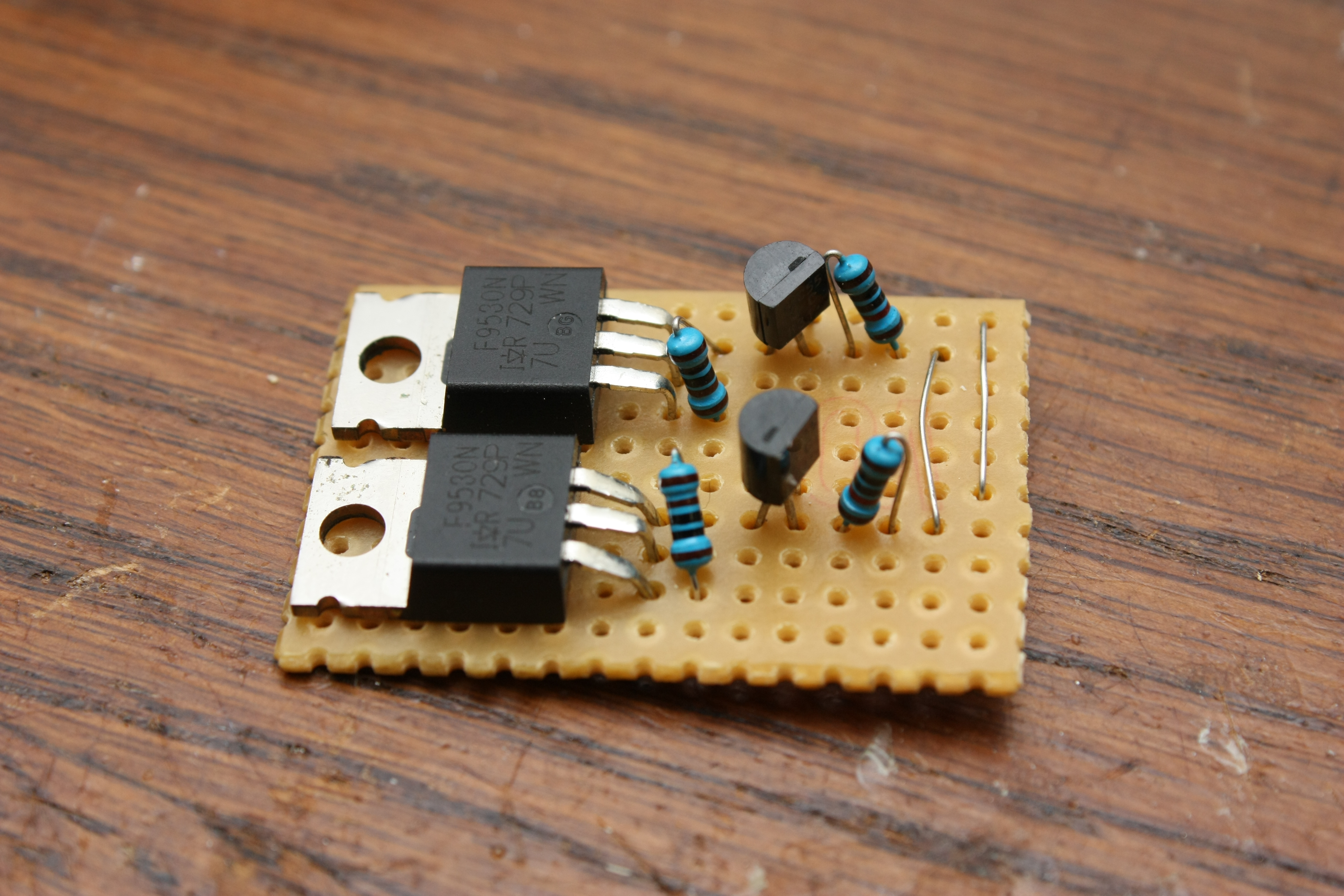
The solution, luckily, is fairly easy: the display logic runs on a 5V and 12V line
from the power supply. If you disconnect these, the display will stop working and
eating power. This little board could do just that: it has two P-channel mosfets on it
which can interrupt the 5V and 12V lines.
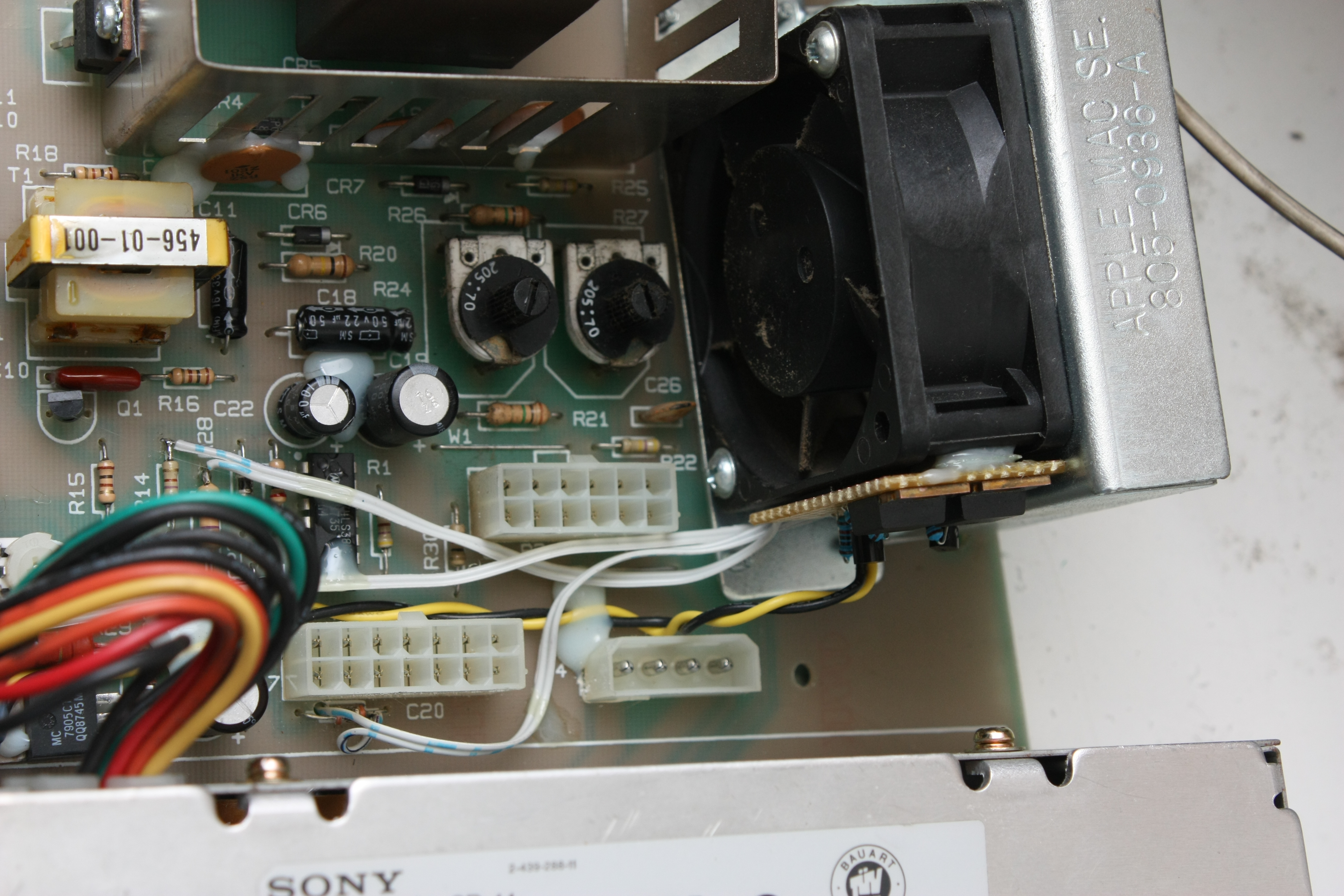
Integrating it into the display PCB was a fair amount of work, but in the end
pretty doable. The little PCB is mounted to the fan with hot-glue.
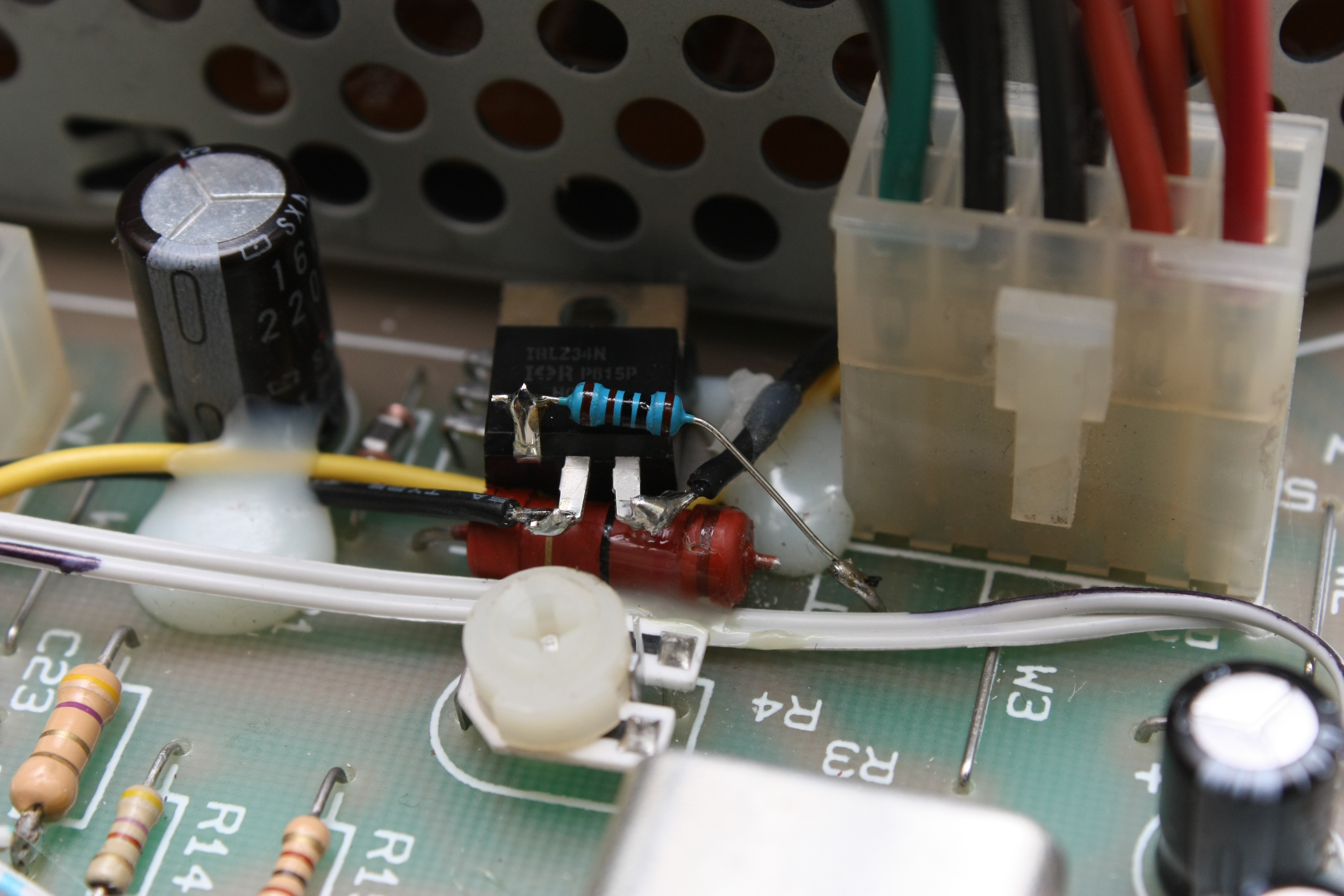
The line to the fan got a similar treatment: a N-channel mosfet controls the power to
it.
I still had to find a way to get the two control channels to the GPU-board, where I had reserved some GPIO-pins for them. The display board already had a 14-pin connection to the GPU, carrying both power from PSU and the video signals. That connection also carried the -5V and -12V rails, which I didn't need. I could nicely re-use these two wires for the control signals. This is what I added on the GPU-board to support it all:
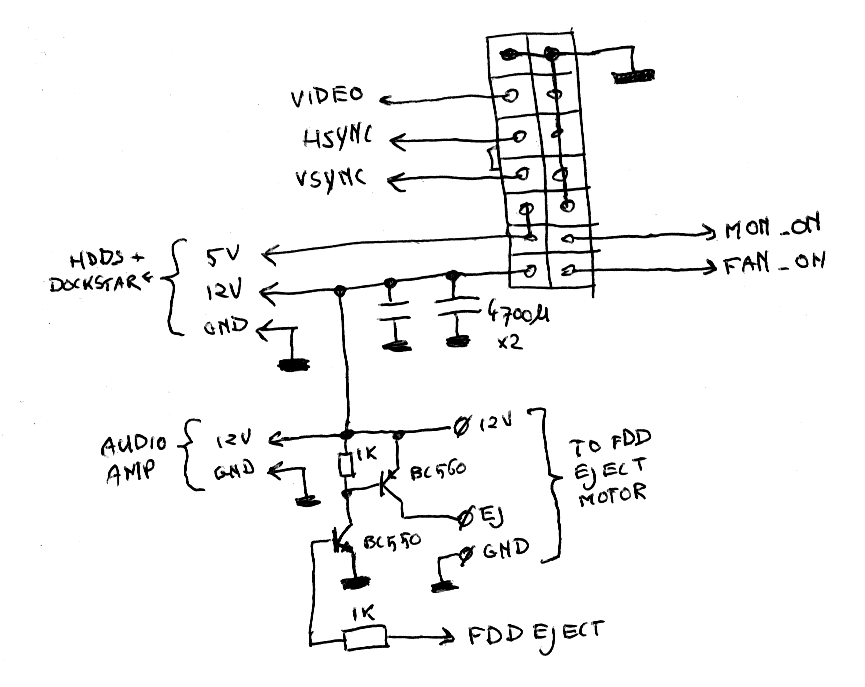
The
incoming 12V and 5V are sent to the Dockstar, HDs and audio amp; the video signal
lines get connected from the GPU ARM. There's one
little circuit left: the eject motor of the floppy drive is controlled with it using
another GPIO on the ARM of the GPU.