Prototype
Ofcourse, some level converters and mosfets don't make a viable printer cartridge controller all by itself. That is why I made a standalone device, intended as a platform to play around with the printer cartridge and everything it can do. It has an ESP32 module, the needed logic to control the printer cartridge, as well as some power supplies to run from a LiIon cell. It's also equipped with some sensors, meant to try to compensate for the not entirely ideal movement human arms tend to make, as well as some buttons and a display to give some feedback to what's going to get printed. Let's walk through the components, if any to perhaps give some inspiration for any printer cart hacking anyone else wants to do:
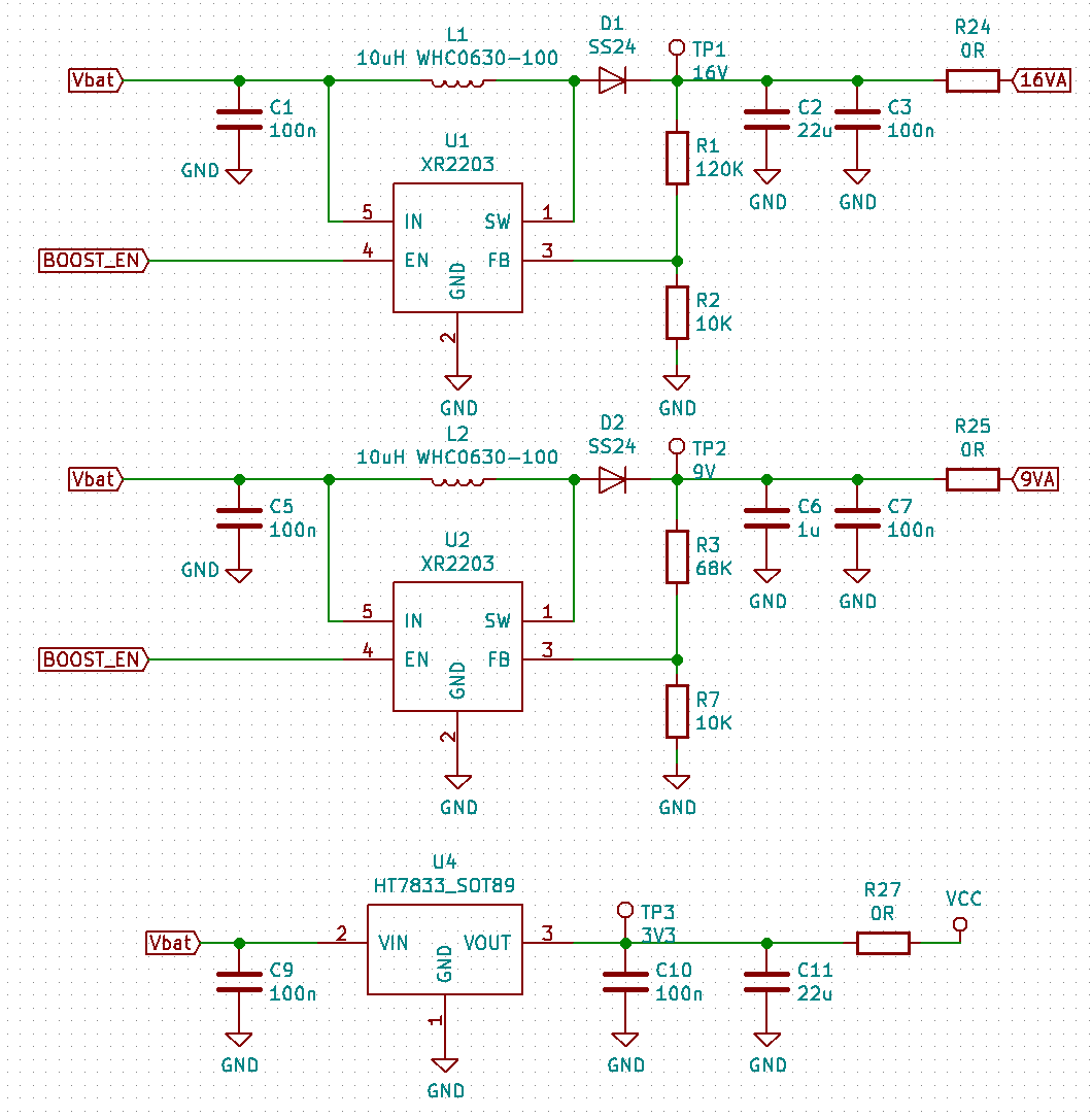
Let's start with the power supply. Power comes in from a LiIon cell and gets converted to 3.3V, 16V and 9V. The 3.3V is needed for the
sensors and the ESP32; it is generated using a simple HT7833 LDO. The 9V and 16V are generated by two boost converters built around the
XR2203 boost converter chip. Note that the 16V power supply needs to work way harder than the 9V power supply; the cartridge only sips a
few milli-amps of 9V power. The reason the two boost converters are dimensioned the same is purely so I only had to buy one type of
components for both.
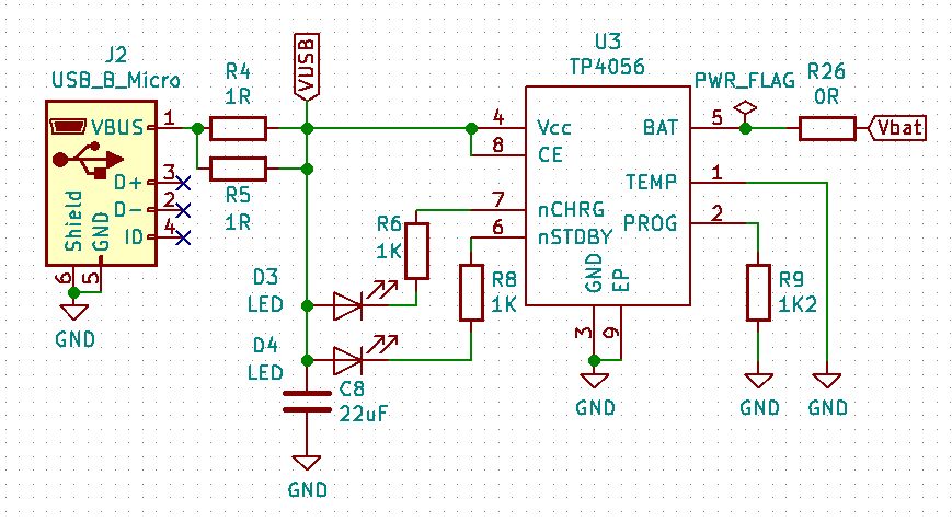
As the entire thing is powered from a LiIon cell, there needed to be a way to charge it as well. I had some space
left, so I added a simple TP4056-based LiIon charger that can recharge the battery from any USB power source.
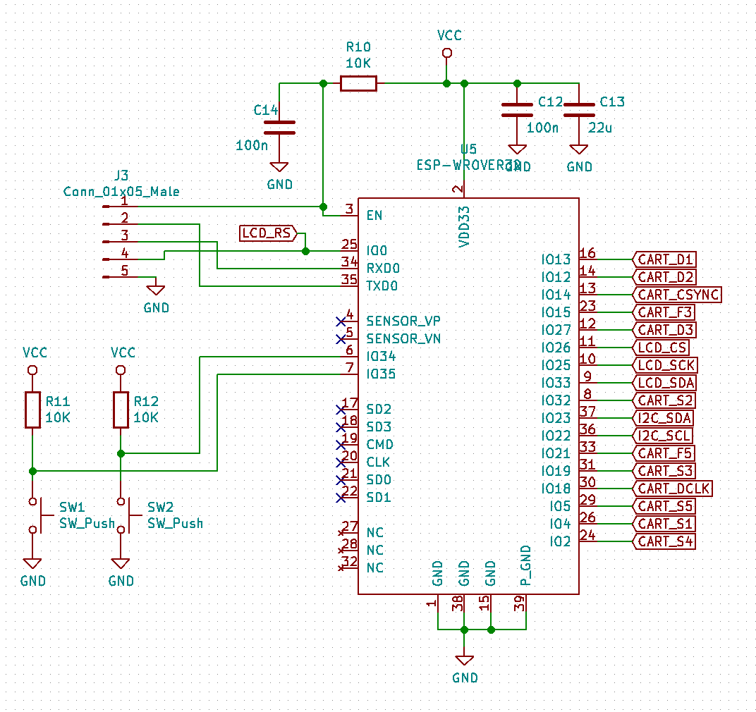
The intelligence of the device is provided by an ESP-Wrover32 module. The specific variant I used has 8MiB of flash and 8MiB of SPI
RAM in it; enough to do some fancy image processing if I feel the need to do that. There's also a 5-pin connector that allows me
to program and debug the firmware on the module, as well as two buttons that can be used to select options and start drawing
when the firmware is running.
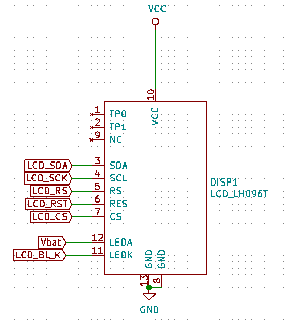
The options that are selected are shown on a small 160x80 color LCD. The LCD has a SPI connection and can be directly controlled
by one of the SPI peripherals the ESP32 has.

This is the cart interface. As discussed before, it's not exactly complicated. All signals can be neatly level-converted by a pair of
MC14504 ICs, one for the 9V and one for the 16V signals. Also visible is the two-mosfet-based level shifter / safety circuit that controls
the dual power lines.
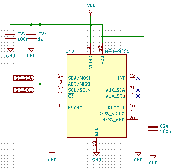
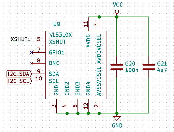
Here's the three types of sensors I used. All of them are connected using a single I2C bus, meaning they only
use up two GPIOs on the ESP32. There's an MPU9250 IMU (accelerometer, gyroscope and digital compass) to measure movement,
three VL53L0X laser distance sensors (only one pictured) which are pointing up, left and right physically.
The idea is that with the combined info, in theory the absolute position of the cartridge can be determined.
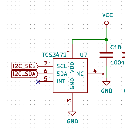
This is useful for, for instance, drawing large images freehand. The last sensor is a TCS3472 color sensor.
The color sensor is next to a white LED; this can be used to 'copy' a color from an existing object, or to
perhaps compensate whatever's printed for the color of the medium printed on.
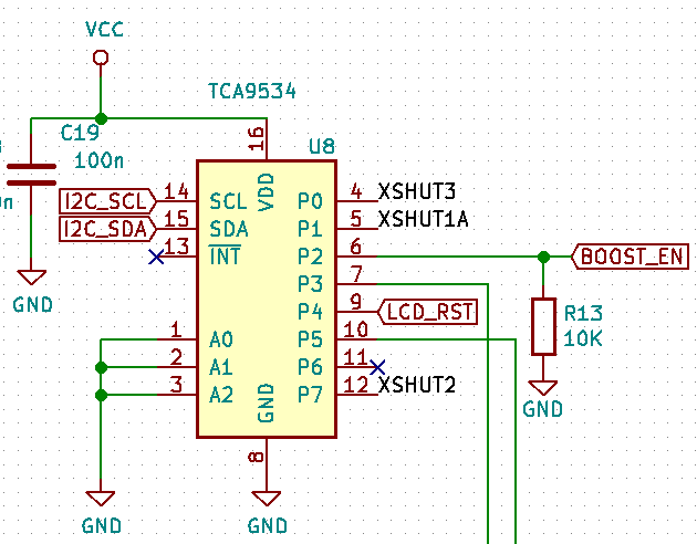
Because I also needed some extra GPIOs, I connected a GPIO expander
to the bus as well. It controls the reset lines for the three ToF distance sensors, the reset line for the LCD, the
enable for the boost converter and (not shown) two mosfets that control the white LED used to illuminate the target
for the color sensor and the backlight for the LCD. The ToF sensors need a separate reset line because they
power up at the exact same I2C-address. However, they do have a command to change that I2C-address after power-up.
By powering them up and moving them to a different I2C-address one by one, I'm still able to control all three
over a single I2C-bus.
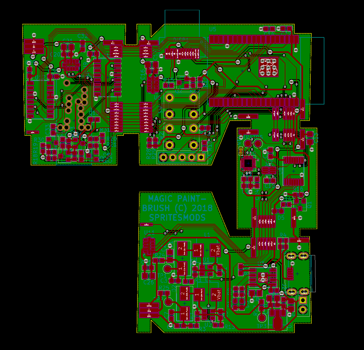
This is the PCB I designed from the schematic. It is in a weird shape as it is meant to be split up in four separate
PCBs that 'fold around' the printer cartridge. They're electrically and physically hooked up; one of the advantages
is that this way, the board house doesn't see it as four separate PCBs and only bills you for one.
Another advantage is that I could assemble the PCB as one piece, and then test it while having all components
in one plane. That stops me from having to precariously balance the assembled unit while debugging. As a small aside:
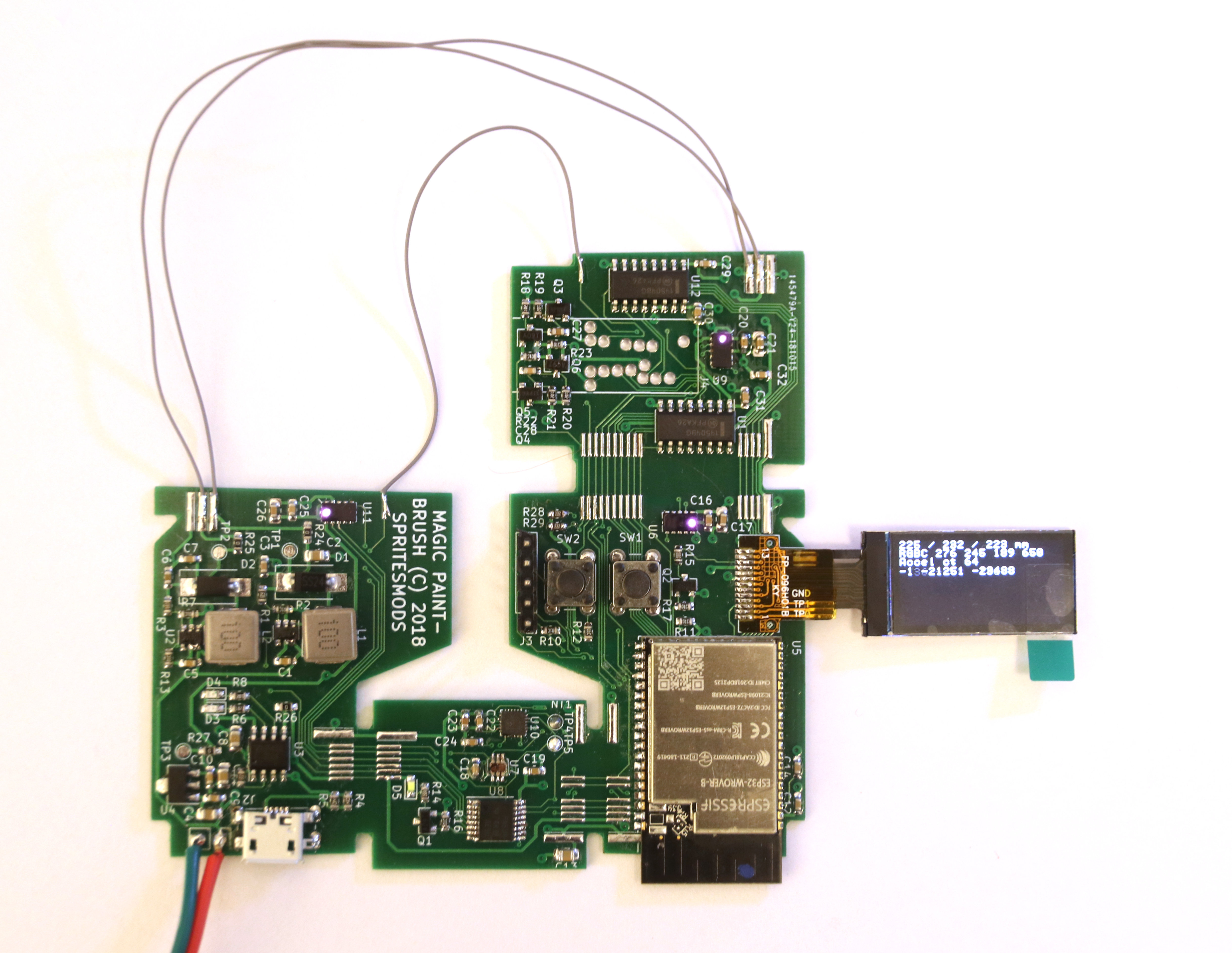
the VL53L0X ToF sensors use infrared laser light, which seemingly is strong enough to penetrate the IR blocking
filter of my DSLR to show up as small purple-ish blobs of light.

And this is the end result when everything is assembled. Note that separating the boards obviously also broke
the connections between them. The boards have small solder pads to run a bit of wire to go across the corner.
Obviously, for anything production-ripe, you'd use a technology like a FPC PCB or flex-rigid PCB technology,
but for a cheapo prototype, this works fine.
If you want to use this prototype as a reference or something to play around with, you can get the KiCad design files (schematic in pdf and gerbers are also included) and build one yourself, or feel free to re-use some of the subsystems as you please.
As this is a prototype, the software is kind-of... spotty. I will share the repository I developed it in, but be aware it is a snapshot of more-or-less my entire development cycle, and it contains everything I used in order to go from the LA captures of the waveforms, to a printed Nyancat and Mona Lisa. Unfortunately, this also means it's a more-or-less undocumented mess, with half-finished abandoned pathways and thing left behind when my knowledge advanced. You can git clone this URL if you still want to dive in.
However, if you're more interested in a drop-in bit of software that can easily control a printer cartridge from an ESP32 (and give you some useful routines if you want to control it from another microcontroller), read on.