More Power!
in most mechanical matters, my instincts tell me: if at first you don't succeed, you haven't applied
enough power. That's why I decided to not let the wimpy LED drivers control the coils anymore, but
to apply some real power, in the form of some IRFZ44N MOSFETs:
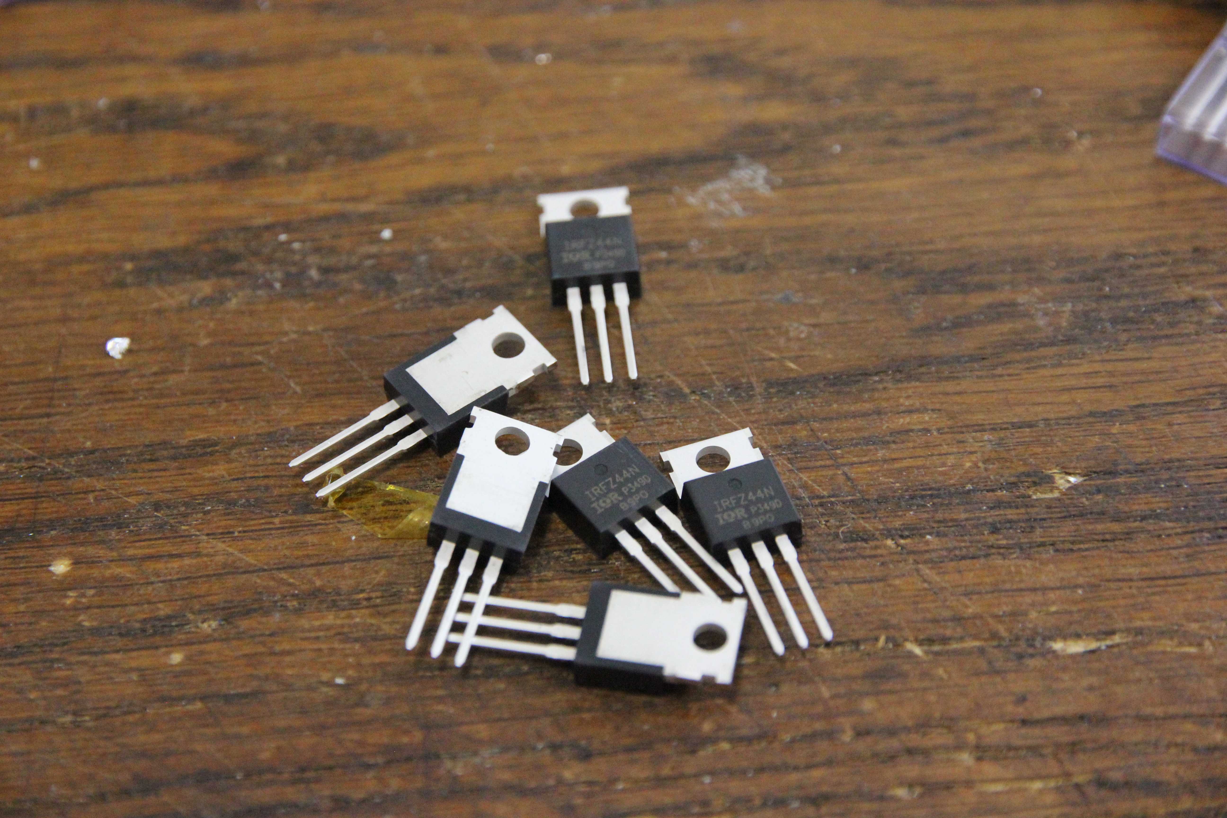
These bad boys can push up to 49 amps into the coils. That should do the trick. Time for a quick
test!
I whipped up a bit of Veroboard with eight of the MOSFETs on it, controlled by one of those shift register
ICs. That way, I wouldn't need to modify the software controlling it all too much, although soldering
without a pre-made PCB is a bit fiddly.
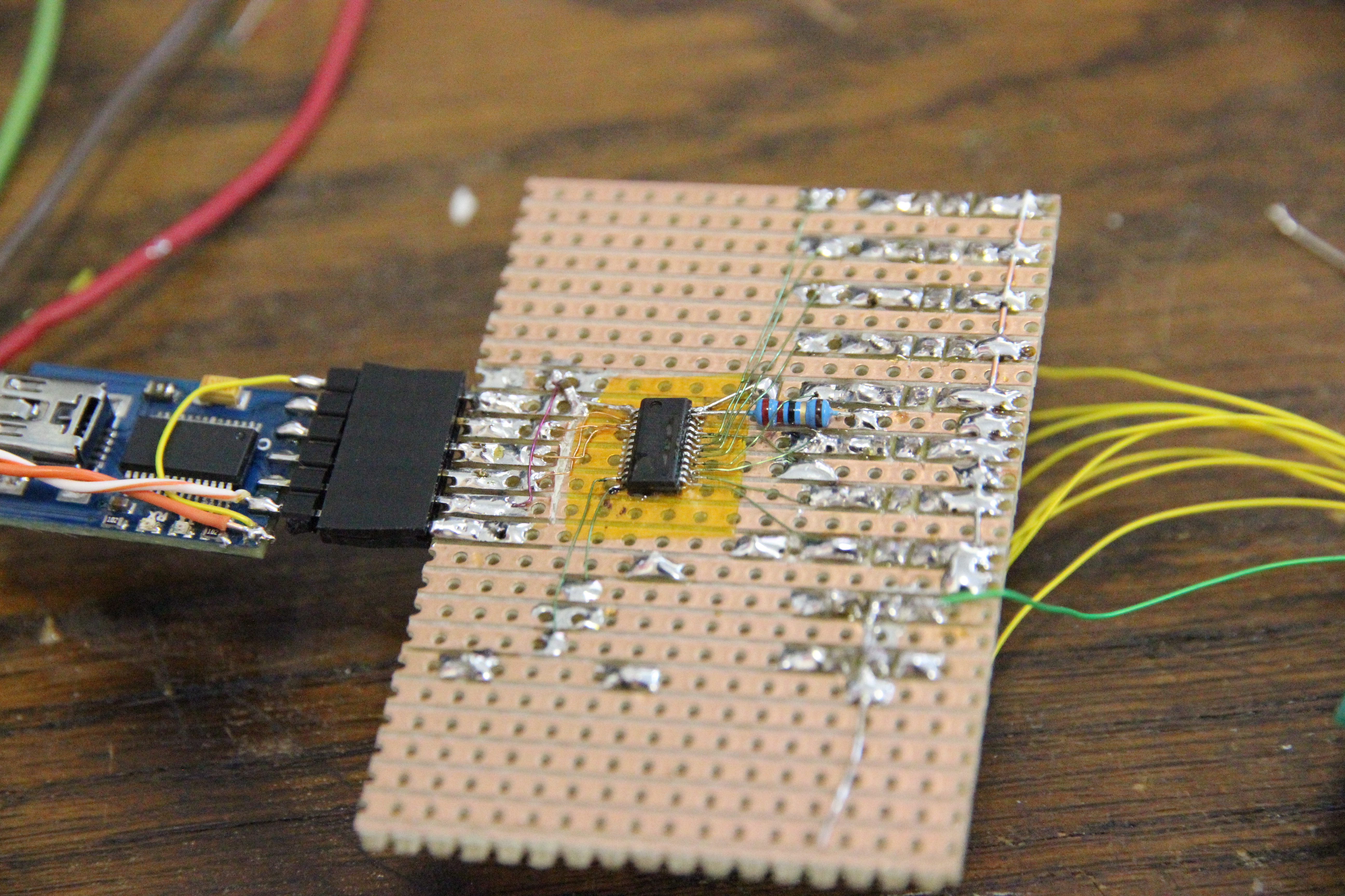
(As you may have noticed, I connected two coils to each MOSFET here. I went back to 1 coil per mosfet later
because that worked better.)
To make sure my new setup could actually deliver enough power, I decided to connect the MOSFETs to the bottom coils: after all, these need to be driven hardest to be able to pull on the magnet through the 1mm of PCB material. I also added a few thousand of uF of capacitance to the power rail; when the MOSFETs turn on, they get discharged over the coils, giving them an extra bit of oomph. All that power seemed to do the trick:
Now my problem was that I would need 80 MOSFETs to drive all the coils directly. My first idea was to
whack all the coils in a matrix. That wouldn't have worked because of ghosting, though. For example,
take this two-row matrix:
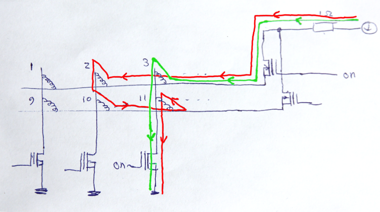
The current through the matrix is switched by the two mosfets on the right, switching the power supply
to one of the rows, and three on the bottom connecting the columns to ground. Say, we want to enable coil
number three. That would mean turning on the topmost and the rightmost MOSFET, making current flow
as indicated by the green line. Unfortunately, the current will also run through the path indicated
by the red line. This will make coil 2 and 11 active and making the current run in the reverse
direction through coil 10! In practice, this means the magnet is repulsed and can actually jump off
the PCB.
Now, I could connect diodes in series with the coils in order to stop this 'ghosting' effect from
happening, but I didn't have 80 diodes capable of conducting the currents I had in mind. This being
more a proof-of-concept anyway, I decided to let go of the idea of putting the coils in a matrix, and
just whacked 16 mosfets directly to the coils, giving me an active surface of about 8x8mm:
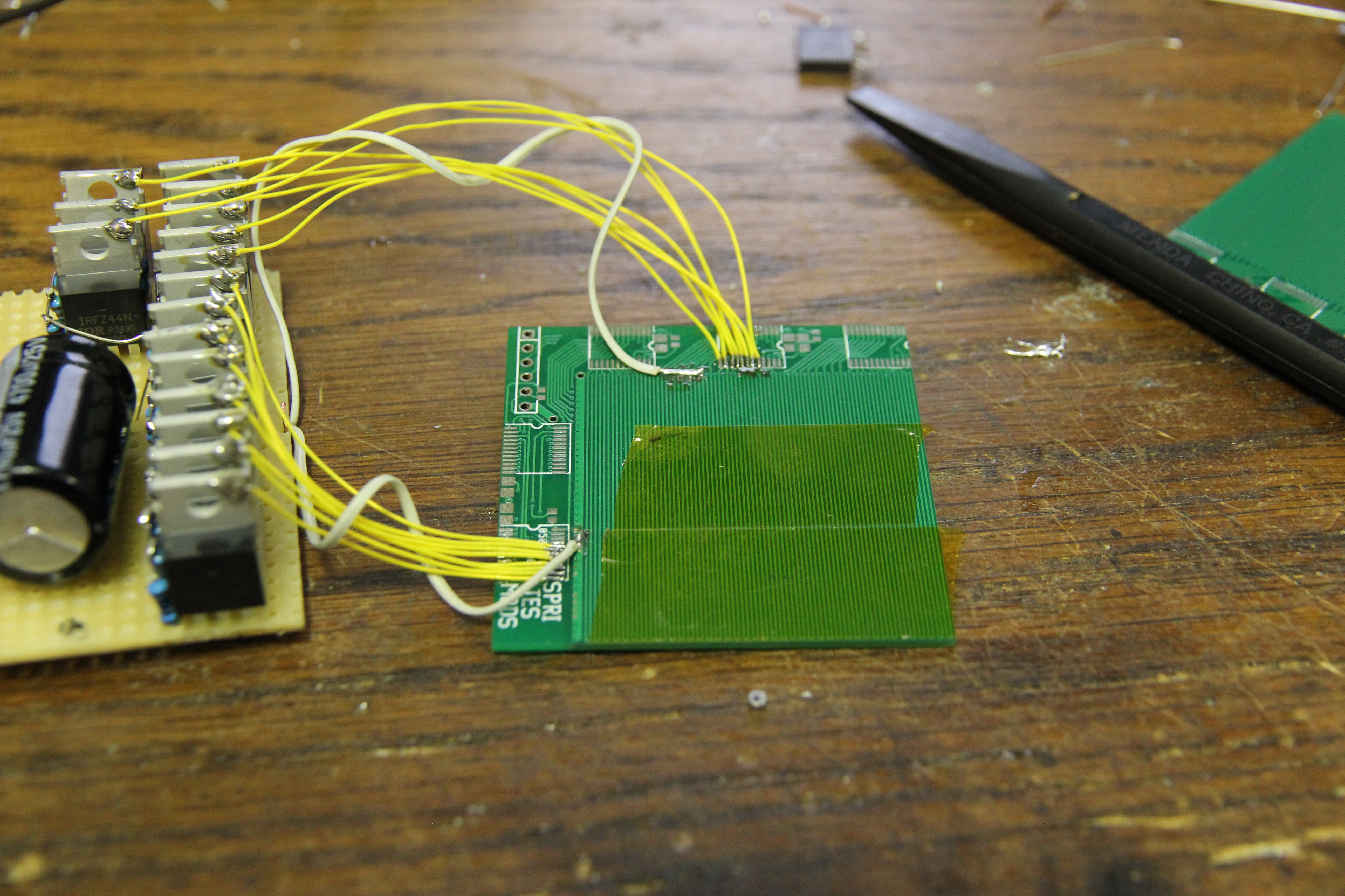
This actually seemed to work pretty well, but I still had some trouble with the coils on the top layer of the board: it seemed that with the coil nearly perpendicular to the magnetic field of the magnet, turning on the current lead to strange effects like the magnet flipping or shooting off the PCB. I solved that by just using two boards sandwiched together, using the coils in the middle of the construction. This also had the advantage that I didn't need to compensate for the differences in coil depth anymore. All this plus some software trickery to do microstepping finally seemed to get the effect I wanted: