Conclusion
Well, it looked like I finally had my own micro-magnet robot plus a tiny bit of controlling surface. I even had a plausible way of matrix-ing the thing, allowing for larger surfaces, by using diodes. And best of all, I had the satisfaction of having solved the puzzle with just a blurry video as a starting point.
Yet the question remained: was this indeed the same way as SRI International used to make their robots zip around and do interesting things? After some research, I found out they have patented their methods, and ofcourse patents are freely available to the public. In this case, patent number 8593016, for a "Levitated Micro-Manipulator System" is the one we're looking for.
Wait, what, a Levitated Micro-Manipulator System? Well, if you have watched the original video, you may have noticed the bots didn't usually actually move on the bare PCB material; it seems a silver-grey material is put over it and the magnets move over that. My first thought was that this material was used to lessen friction, and in a way I wasn't wrong. According to the patent, the material is diamagnetic. A diamagnetic material has the property that it will basically repulse any nearby magnets, which means that if you have a strong diamagnetic material and a strong magnet, you can make the one float on top of the other one. By using this material, SRI nearly eliminates friction and can use currents of a few mAs to move the magnets around.
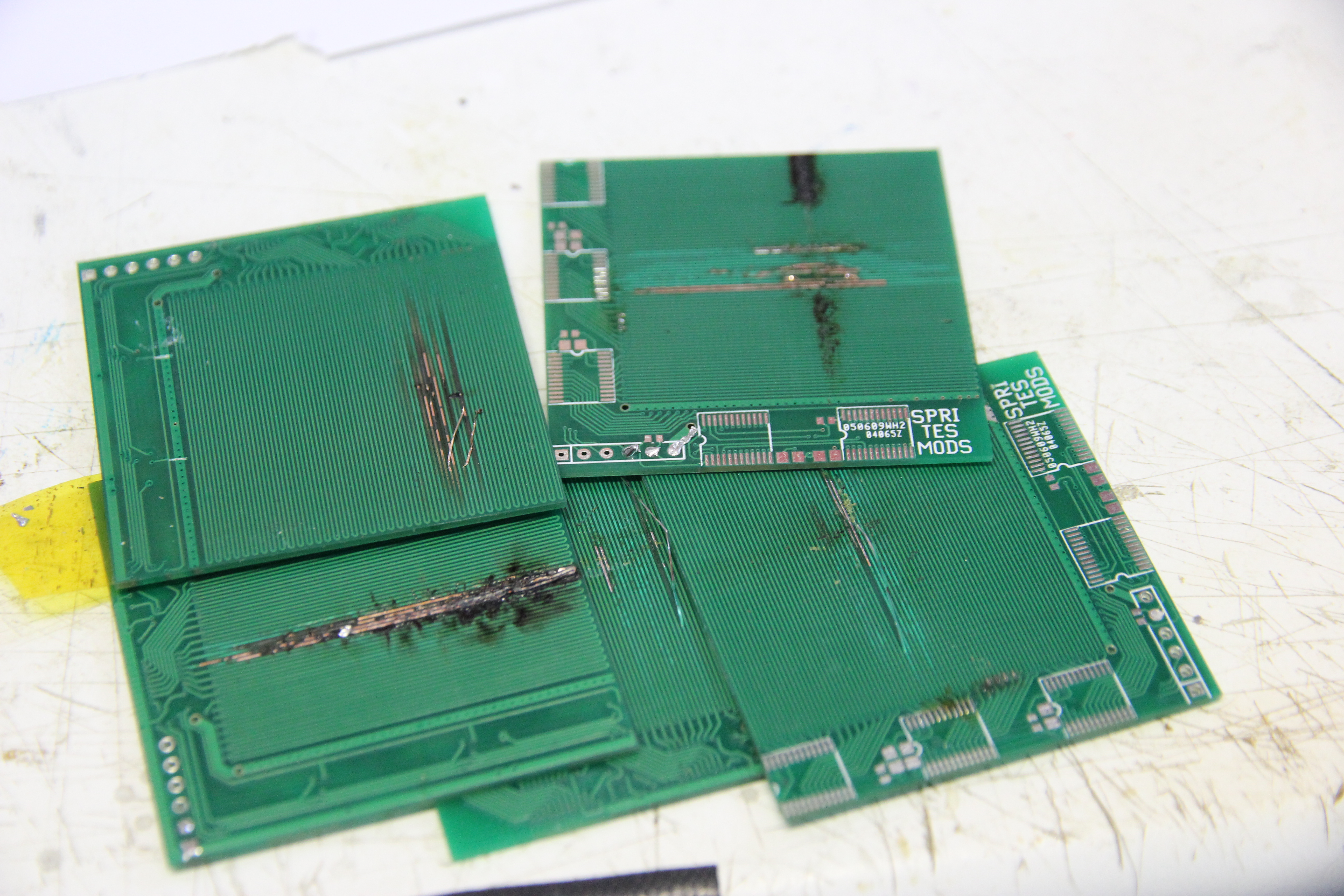
I presume the advantages of needing only a few mA to move the robots around are obvious. If not,
here are the unfortunate victims of me trying to push too much power through the PCBs:
In case you want to improve on what I did, you can download the archive with the PCB designs and the programs I used to control my PCBs, and if you manage to get better results than I have, I'd appreciate a note.
« Prev 4
15 commentsSoon controlling miniature F1 race cars ... https://www.youtube.com/watch?v=xPUEOhMBpUw
For levitation,Is it possible to use "Magnet spring"? please reference to https://www.youtube.com/watch?v=IANBoybVApQ
Large electric motors often use overlapping field coils. Like, imagine A,B,C represent three different windings, the coils might be wound like this: +A -C +B -A +C -B ... You might be able to use the same principle to have every row + column energize multiple windings, just centered around different points, rather than individual lines. Then you could use less current.
Maybe use andre geims sellotape method to make thin graphite Sheets using the plastic graphite available on ebay and parcel tape
PG makes sense, relatively cheap and can be sourced in large sheets. I did wonder about using a PG/Bi layered material as both are diamagnetic so using a thin sheet of pyrographite and smooth bismuth on top would work well.
Nice work! In the video, they move more than 1 robot at the same time. How is this possible with only layer of pcb? https://www.youtube.com/watch?v=uL6e3co4Qqc#t=55
Are you sure the metallic looking foil is a diamagnetic material? To me it more liked the ferrite sheeting we have here for shielding wireless charging systems here. This is often used to lead away field lines or actually focus them.
Hi! Very nice experiment. I think, your idea using a coil/a loop might be a problem. The dimension of the traces are much smaller then those of the magnet. In this case the magnetic force is the sum of back and forth current and they will partially cancel out. If you look at at figure 18 and 19 in the patent you can see that the traces and the magnets dimesnsions are very fine adjusted. In the video of Mike's Electric Stuff traces and magnets nearly have the same dimension and he does not use a coil. So magnetic force will only apear to one pole of the magnets.
Any idea what kind of diamagnetic material SRI is using? I assume bismuth foil since they're using a flex-pcb in the video and it seems plenty flexible. Pyrolytic carbon is the other alternative that comes to mind but its pretty brittle.
Add ultrasound (or knocking, or something similar) and you will have a zero stiction board for your pet magnet to frolic around. And make the board smooth (since the top side traces are not used anyway). Or just add another smooth layer on top. To manage with less FETs, wire every Nth parallel 'coil' in series. The robot is only interested in the ones currently :-) below it.
In the SRI video it looks like they are using a thin sheet of pyrolytic graphite over the PC traces. It has very low friction, and is diamagnetic. It will float on a strong magnet.
You might actually be able to pull this off without a custom PCB. I initially thought that it was built off of a Wacom drawing tablet PCB as the majority of the board is a grid just like your PCBs.
Imagine using this to move things in H0 scale model railway diorama. I am definitely going to try this next year.
Hi. As you have certainly witnessed in your everyday life, you can beat the friction down at will by using vibrations (e.g. loud sound). However, it agitates everything on the plate, so you need to keep robots (which you don't want moved) activelly attracted to their designated positions while vibrations are on. Regards, salec
Another version here: https://hackaday.io/project/154496-2d-actuator-move-micro-robot-in-xy-2d-space