Electronics
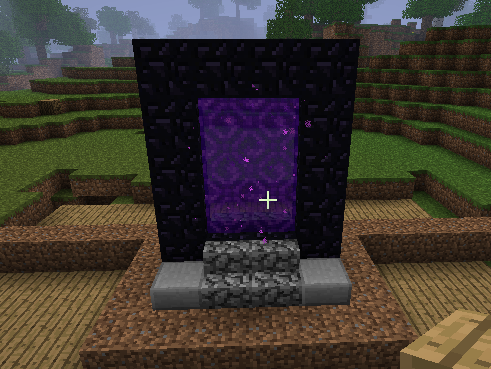
So, what would I have to display on the TFT to make it seem like a real Minecraft
portal? Here's an in-game one for reference:

The outside is made of a dark material called 'obsidian', and within there's a
transparent swirly texture. Some particles spawn on the outside in front of the portal,
slowly floating inside.
The outside of the portal, plus some extra ground and decoration, can be made from wood. The inner portal texture, though, has to be animated: the LCD should go there. In-game, the swirl texture is somewhat transparent; unfortunately, I can't really get the TFT to display transparent pixels, so that effect will have to be forsaken. I also can't display particles floating in front of the LCD, but that effect can be faked a bit in 2-D.
All this animation does mean the LCD will have to have it's contents refreshed fairly quickly: even at a somewhat meager 10FPS, 10*320*240*3 bytes will have to be uploaded every second, totaling at about 2 megabyte per second. That's something yer olde average AVR probably won't be able to sustain, so I had to grab something faster.
Recently, I got a couple of STM32F101CBs as a gift. These beasties are quite nice:
an ARM-core at 36MHz surrounded by 128K of flash and 16K of RAM: they ought to be enough
to generate some nice graphics. Because generating graphics is about everything the
electronics needs to do, the schematic can remain simple:

On the left, there's the STM32F101, on the right the Nokia LCD. The two are directly connected, with only a resistor on the PB2-pin: this pin has a double function on the STM32 as 'BOOT1' which has to be pulled down to get into the bootloader successfully. In a real phone, the LCD would be fed 1.8V on Vio and 2.5V on Vaux, but in most of the datasheets I read the Vio could be as high as 2.9V. The STM32 is happy with any voltage from 2.0 to 3.6V, so I decided to just feed everything off a single 2.5V line. This voltage is generated by a LM1117-1.8 linear power regulator, feeding off the 5V suplied to it by an USB-cable. This chip normally outputs 1.8V, but with the addition of a diode biasing it's ground pin by 0.7V, it happily outputs the needed 2.5V instead.
The LCD is lit by a few internal white LEDs, which need a current-limited voltage of about 7.5V to function. This is generated by a very barebone boostconverter consisting of an 100uH inductor and the logic level N-channel-mosfet inside an IRF9952. (You can use any other logic level N-channel mosfet instead, by the way.) This boostconverter doesn't have any feedback: the STM32 just outputs a fixed square wave to feed it. The STM32 also needs to be programmed: I use the internal bootloader for that. The bootloader gets invoked when the STM32 resets and the BOOT0-pin is pulled high. Normally, the BOOT0-line is pulled down by the 10K resistor and the STM32 boots directly to it's program, but as soon as the serial port is connected, the idle voltage on it's TxD-pin will pull the BOOT0-pin high and the STM32 can be reprogrammed.