Schematic
With the display hardware fixed up, the hardest part of the hardware design was done. Now we only need to
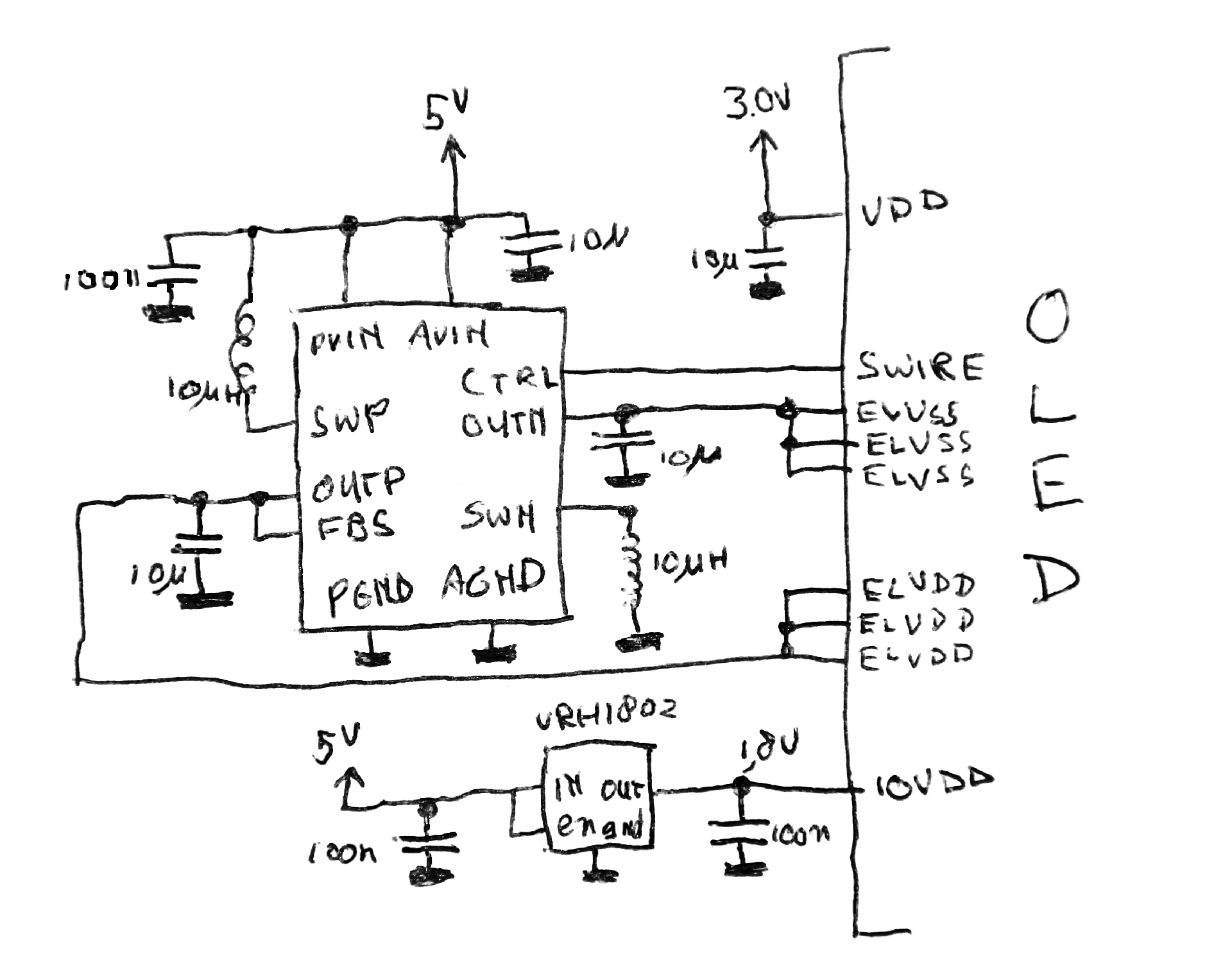
add the rest. First up, the power supply. This is pretty simple: I feed the entire design from 5V from an
USB-to-serial converter that I also can use as a debugging/programming interface. That voltage is
taken to generate the +4.6V, -3.4V and 1.8V the OLED screen needs, as well as the 3.0V to feed the ESP32. The
+4.6V and -3.4V are generated by a TPS65631 chip, and a reference schematic for that was included in the
datasheet for thr OLED. The other voltages are generated by a pair of simple LDOs.
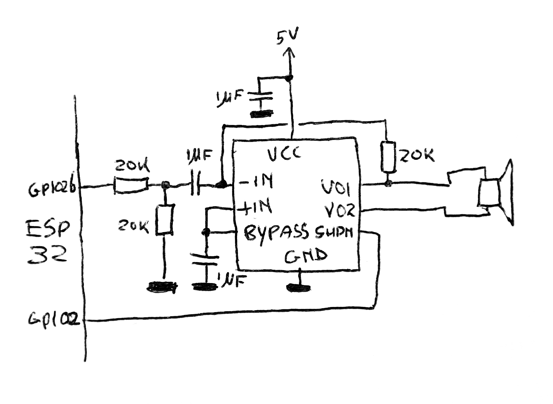
The Macintosh also had sound. The quality isn't that good by modern standards (22KHz, 8-bit) but the sounds
that various software programs make are by now quite iconic, so I couldn't forego a speaker here. The ESP32
has a built-in 8-bit DAC, and that is used to render the analog soundwaves that the emulator generates. That
then gets put into a NS8002 which is a 2W class-AB audio amplifier housed in a small SOIC8 package. It is cheap,
needs very few support components and makes more than enough noise for the tiny Mac to attract attention.
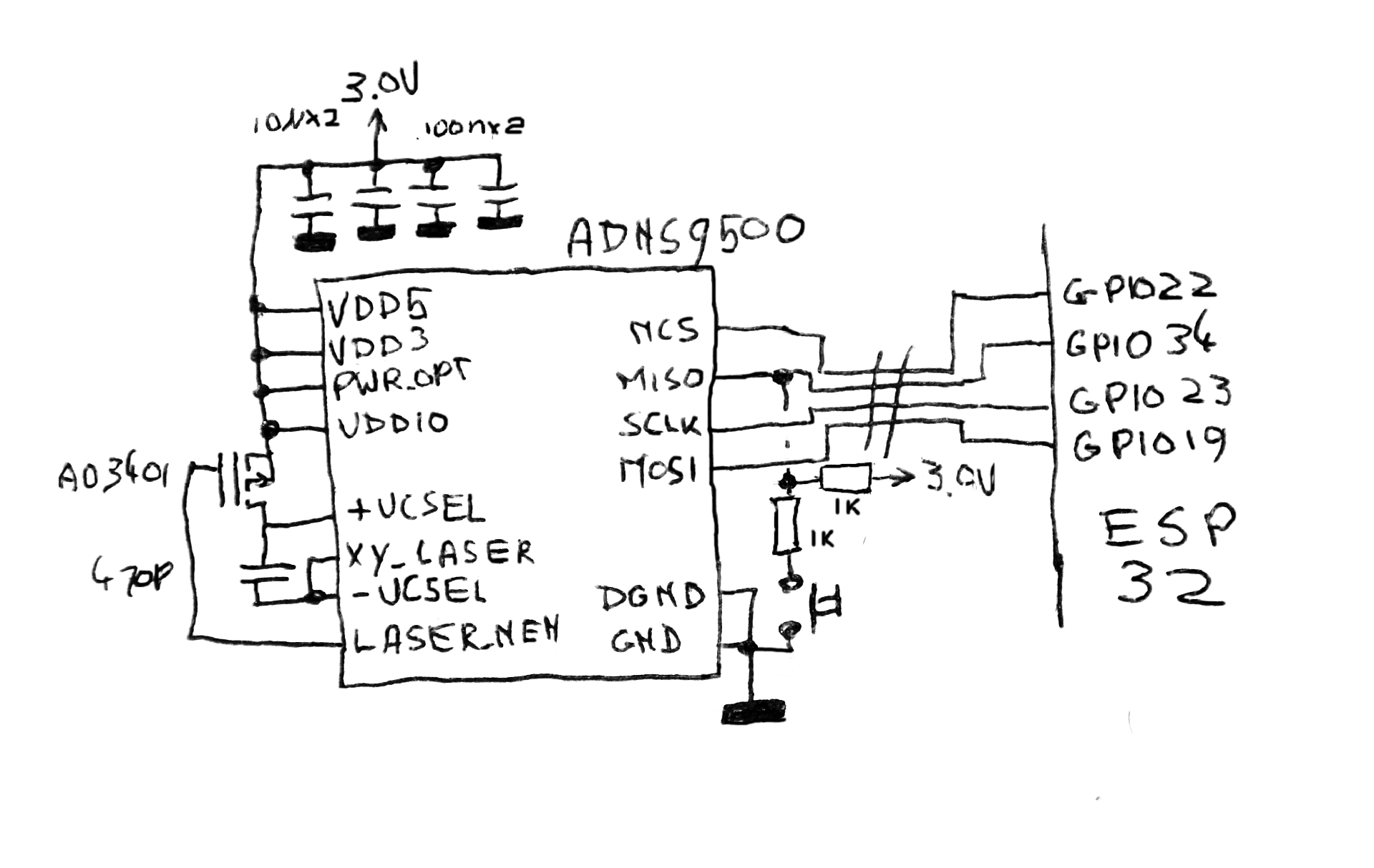
One of the things that made the Macintosh so revolutionary is that it was one of the first commercial computers that came with a mouse. The Macintosh team thought so highly of the mouse that essentially the entire OS is based around mouse-controlled UI elements, and unlike, for example, an IBM PC, it is entirely possible to control the entire Macintosh with only a mouse. Obviously, my tiny Mac should also have such an important peripheral. I still do remember the original ball mouse that came with the early Macintoshes, and I do not quite relish the need to get the gunk off the little rollers every so often; there is a reason optical mice have replaced these mechanical devices entirely. This also has the advantage that parts for these new-fangles optical mice are quite easy to obtain: I did not need to spend much effort at all to locate a source of ADNS9500 gaming mouse sensors plus the corresponding optics, for instance.
The other nice thing is that an optical mouse sensor is a pretty deeply integrated device: a mouse sensor only
needs a few other external components to function, and the schematic reflects this. There are a few capacitors
for voltage stabilization, an MOSFET (copied straight from the datasheet) to switch the laser diode, and some
other jellybean parts. The mouse sensor communicates using a four-wire SPI signal, and I've re-used one of these
wires to also send the mouse button signal over: the MISO pin is pulled down with a fairly
strong pulldown when this button is pressed. The value of this pulldown resistor is not enough to stop the mouse
sensor from communicating, but it is enough to overcome the pullup-resistor that normally pulls up the line, so when
the sensor tristates the MISO line, the ESP32 can detect if the button is pressed.
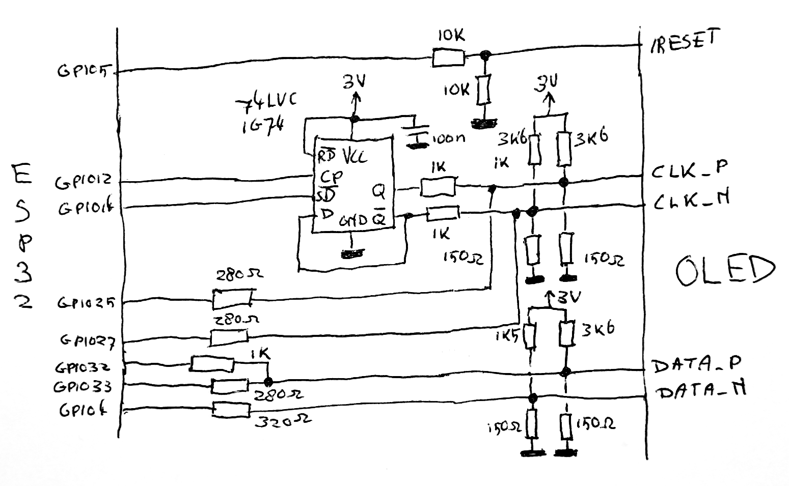
Finally, the OLED screen needs connecting. We already did all the hard work calculating all the resistor values,
so the schematic should be more or less self-explanatory. The chip added is a D-type flipflop and is used to halve
the clock rate: as mentioned before the MIPI standard needs a new data bit every time the clock polarity inverts,
while the ESP32 can only send out a new one on a raising or falling edge.
With the schematic drawn, I moved on to the PCB artwork. The display I chose was meant to be mounted to its
controlling PCB, with the connector on the backside of that PCB. While that would not leave much room for the
other components, I still wanted to put all the other components on the other side.
![]()
It's a good thing I have a good pair of eyes and a hot-air rework station: this allowed me to
use 0603 components which made everything fit cleanly on the limited PCB space. Especially the connector
for the display and the QFN OLED power supply chip would be pretty hard to do with a normal soldering
iron.

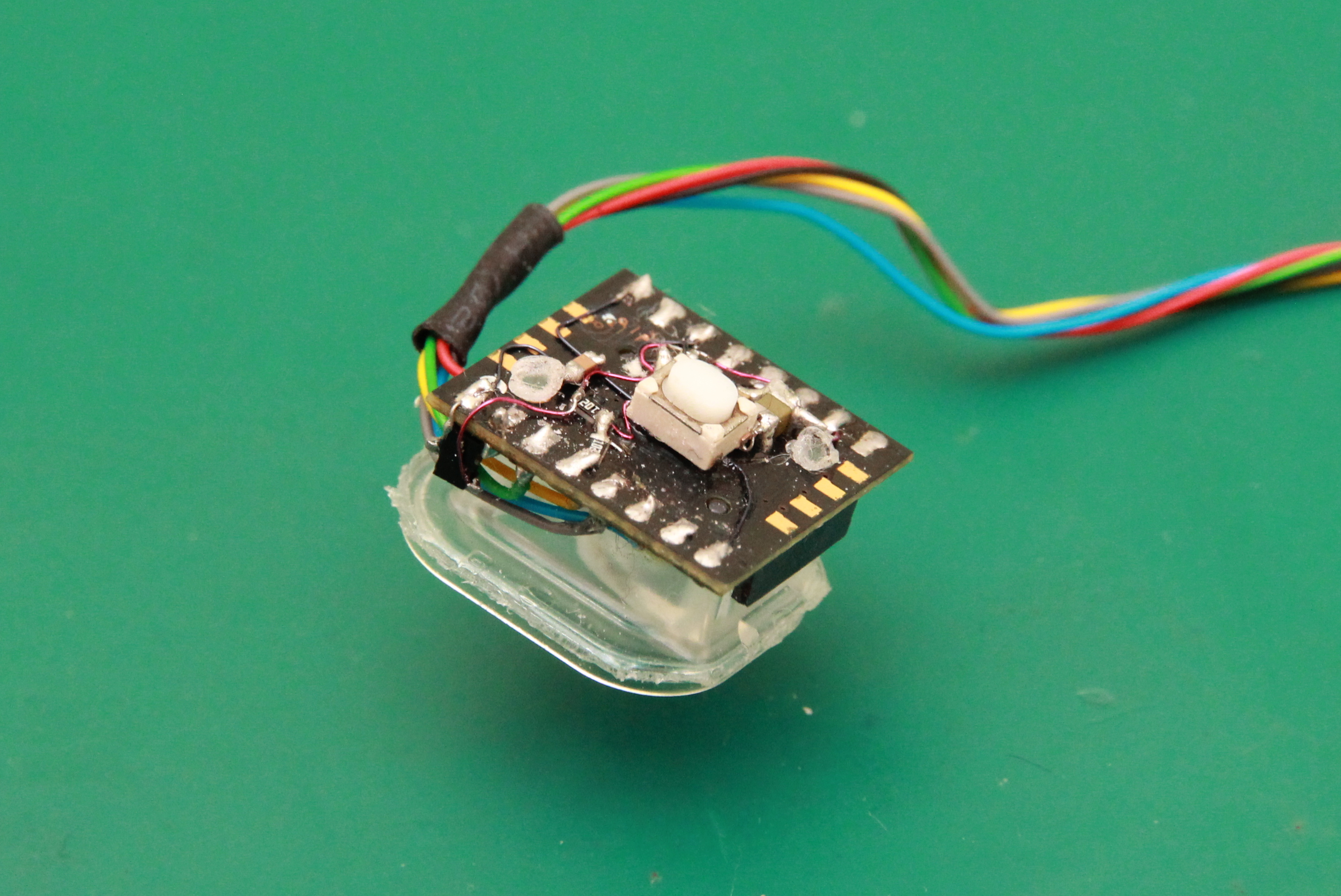
For the mouse sensor and attached components, I figured out using a PCB would use up too much space.
Instead, I opted to solder all components on the sensor itself, freeform style. This way, everything
should be able to fit in the mouse.