Making the case
Meanwhile, we finally managed to get the documents to be able to return to China. After a fourteen-day quarantine, we arrived back home and I had access to all my usual stuff. Time to free this build from its devboard and put it into a nice case!
First of all, what form factor to use? The PDP11 itself came in various form factors, from big hulking cabinets with giant tape reels down to µPDP machines that more resemble a PC than anything else. One thing in which they differ from a PC is that they do not have a standard keyboard and monitor interface: instead, you would have to connect some kind of external serial terminal to the machine to work on it interactively.

So I thought that for a device that's mostly there for its looks and interactivity, perhaps I'd house it in one of the things users would mostly look at it: an age-appropriate serial terminal. I decided to pick the DEC VT-100 here (actually specifically the more common DEC VT-102) as it has a very nice industrial look and is easily recognizable. Additionally, actually hiding the entire PDP11 into that terminal wasn't without precedent: the VT-100 range was designed to be expanded, and e.g. the VT-103 could incorporate a small PDP11 system. In the case of the miniaturized PDP11 I was building, the VT-100 would give me ample room to put in the logic board and some more.
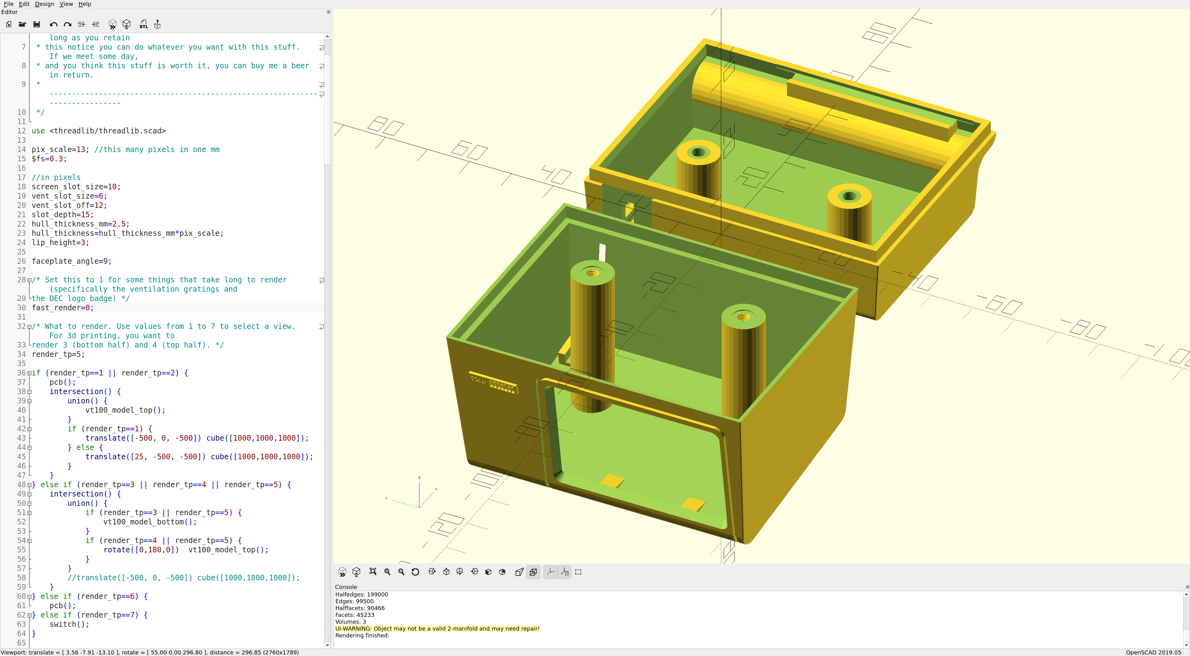
On to designing a VT-102 case. I effectively grabbed some pictures off the Internet and used these to model the case in OpenSCAD. The case does not have any non-trivial compound curves in it, which is good because it allowed me to model it using only a front- and sideview image. This gave me a more-or-less real-size model of the VT-102, but obviously I wanted to scale it down to a miniature version. But scale by how much? Well, that's mostly dependent on the display I wanted to use as it needs to fit in the display bezel of the case; all other parts are inside the case so I can move them around as needed.
I found a really nice 1.8" 320x240 LCD on Taobao that happened to have the same controller as my devboard, so it would be an easy fit. (I also found an 1.3" 240x240 display. In theory, with subpixel sampling, I could actually get the text to show up halfway readable, but the entire thing was just too small... As an indication, the metal thing is a Micro-USB plug.) As the size of the display was the main constraint, I could now scale the VT-102 down to fit this display. (As the original VT-102 had an 12" display, this makes my model roughly a 1/6.6th replica. Which is nice, as that's also the scale of my MacPlus model, give or take.)
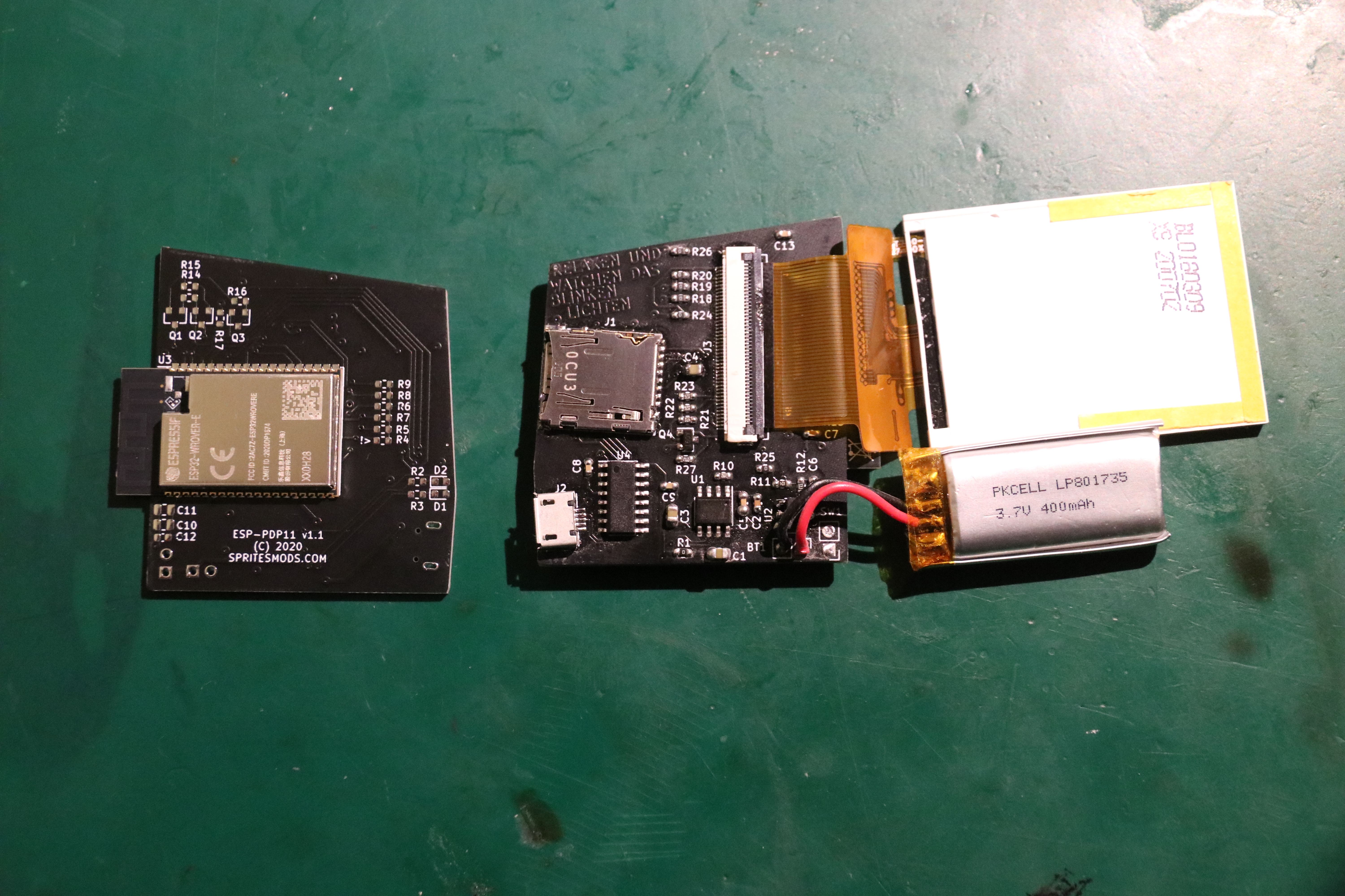
As I now know the size of the case, I could build the schematic of the electronics and design the PCB they would go on. The PCB could sit in the side of the case, allowing the connectors to peek out of the case on the back. It also meant that the FPC of the LCD could bend under a 90 degree angle and then terminate on the PCB in a connector. The components on the PCB are nothing special: an ESP32-Wrover module as the brains, a CH340 USB-to-serial chip to program the flash in the module without having to externally connect a programmer, a LiIon charger and a 3.3V LDO. There's also a micro-SD-card slot for the storage for the hard disk, as well as the FPC connector for the LCD.
A while later, the components I needed as well as the fabricated PCBs came in. The big FPC connector was a bit of a pain to solder, but all the other components
went on fairly quickly. (And note that this is the second version... the first version... well, something
with a mirrored pinout on the FPC connector. Don't ask.)
In order to hold the LCD and the PCB in place, I designed some slots where the corners of the PCB and
the edges of the LCD would fall into. I also cut the case into a bottom and a top half, to be printed separately. There's an interfacing lip
on the bottom and top half that fit over eachother, guaranteeing that the two halves will fit well
together without any weird cracks. I also added two screwpost terminals to securily join the
two halves together. My printer actually is just about precise enough to be able to print half-decent
M3 screw threads, so I also put those in: no inserts needed that way. That way, assembly is trivial:
put in the LCD, put in the PCB, close case, done. Well, aside from the on-switch and the battery.
The on-switch is so far away from everything else (because it looks nicest there...) that it's just
resined into it's own cubby and the LiIon... well, as I didn't know what LiIon to put in, I didn't
really carve out a place for it. I imagined I could just double-side-tape it somewhere.
Printing the case took a while, mostly because I didn't realize that resin fails to solidify
in interesting ways when it is too cold. Given that I also selected a color I hadn't used before, and that
I wanted the outside to have no supports spoiling the nice surface, I had a few too many failed prints...
these here are the final ones, from a warmed room and printed with enough exposure time.
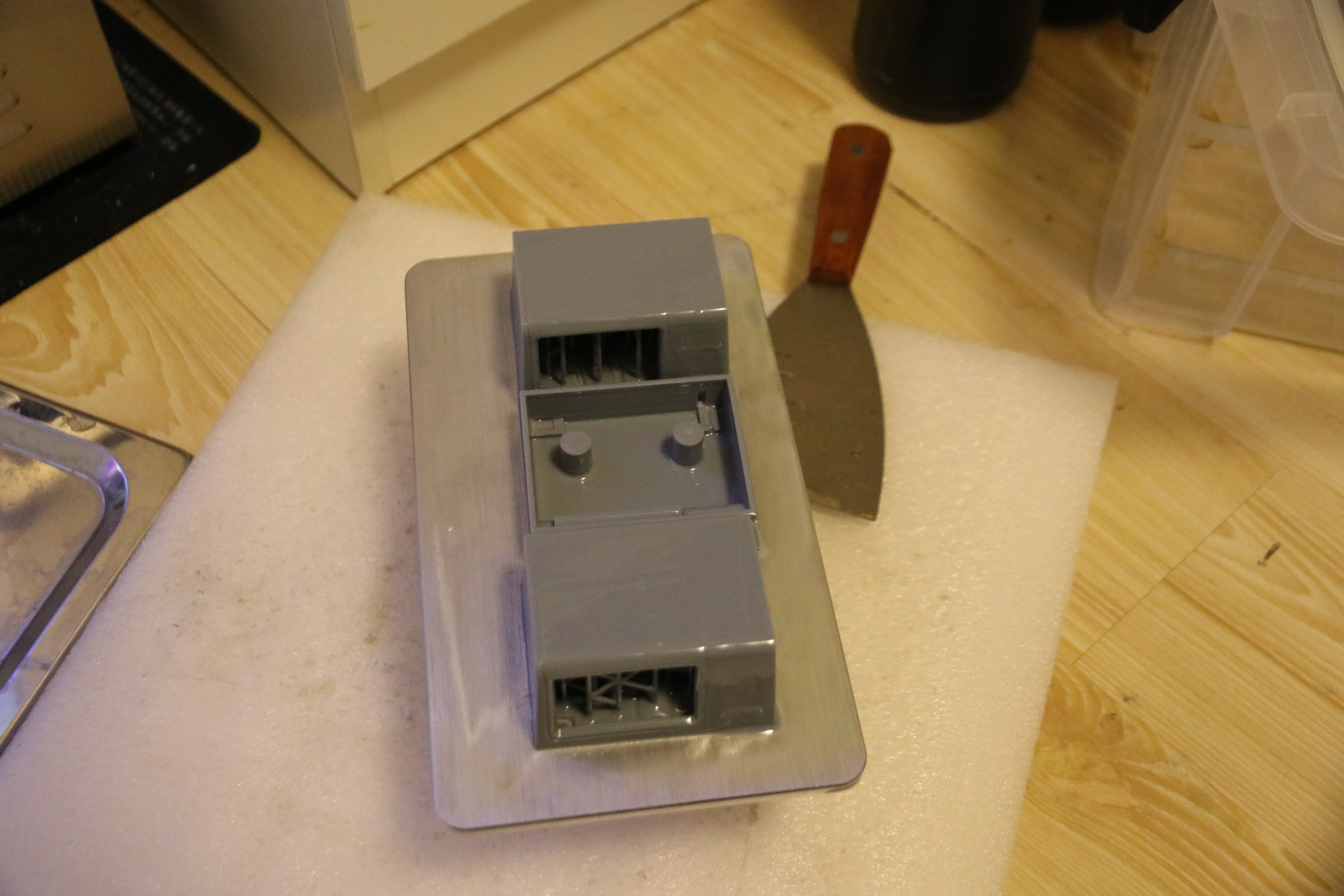
The base color of the print is likely a bit off, given the fact that most images of the PDP11 show a
more yellow-ish color, but this resin came closest and I found it hard to find paint that approximated the
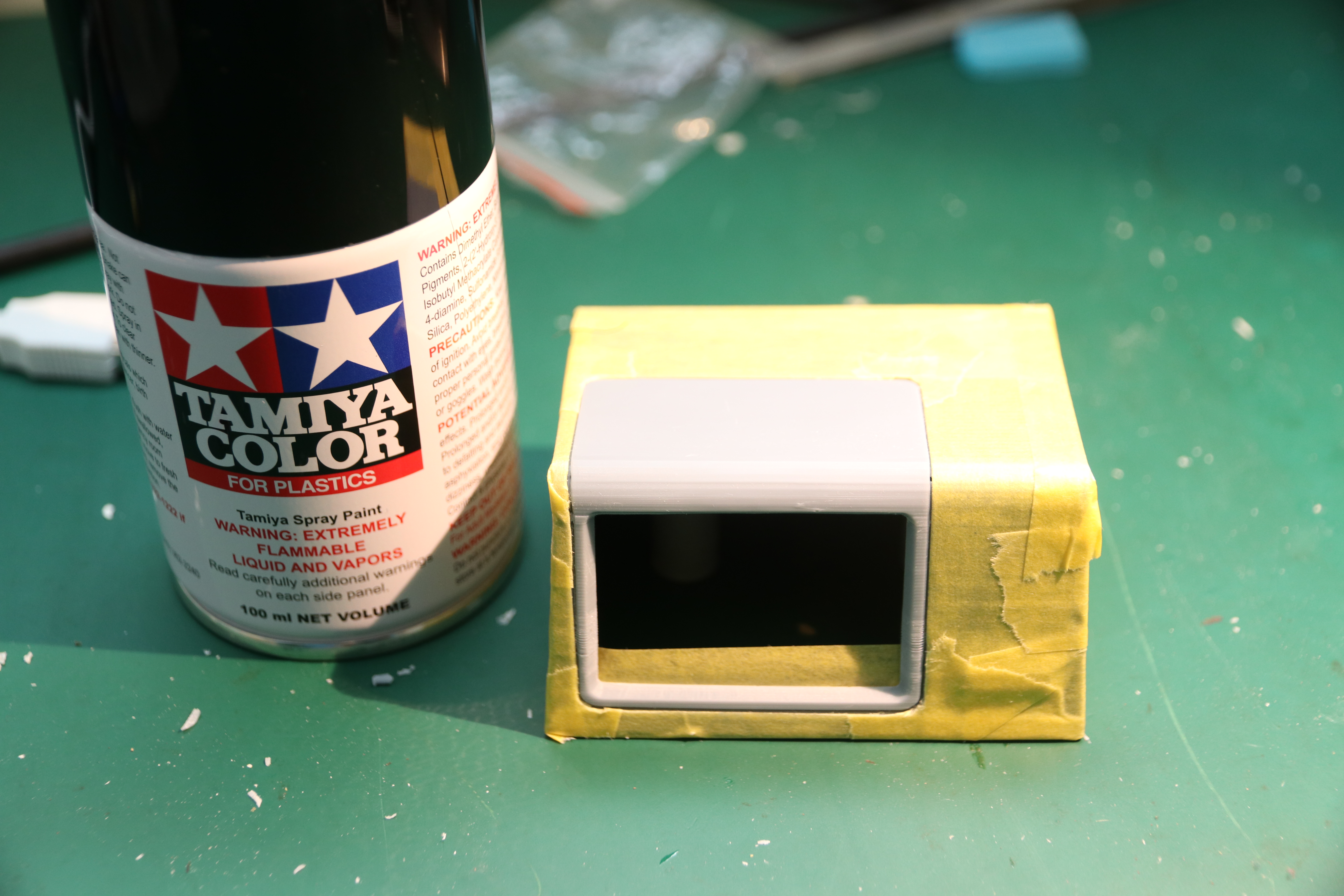
color and texture better, so I left it at that. However, the iconic black bezel around the CRT wasn't something
I wanted to skimp on. Luckily, it only cost some masking tape, careful cutting and a can of black spray paint
to get that approximated well enough.
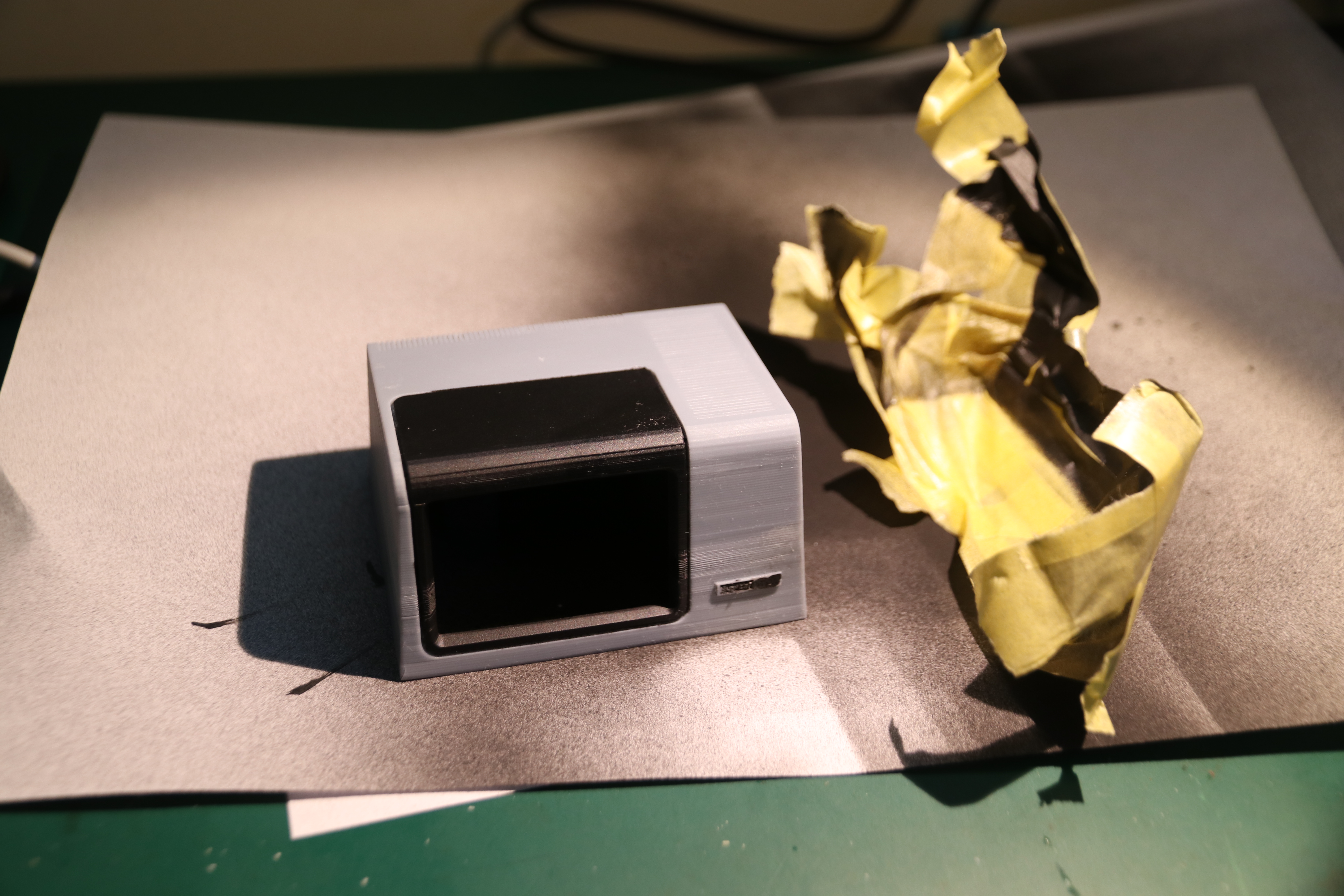
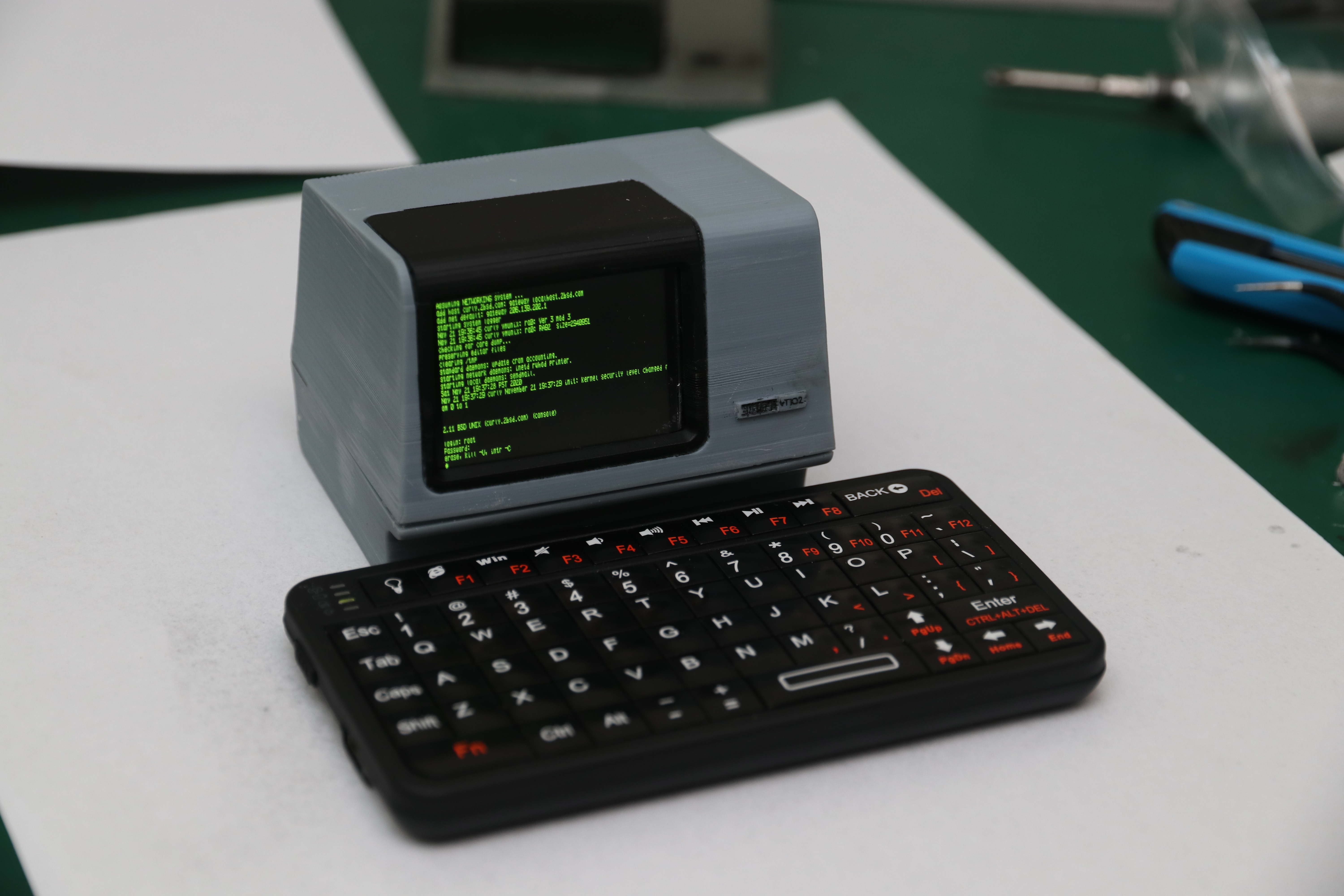
And here is everything built in and closed up. There actually is a little 'Digital VT102' logo on the front, which needed some black paint
to come out right, but is actually almost readable.The keyboard in front of the thing is a little credit-card sized
Bluetooth keyboard, which actually is a bit too large considering the scale of the VT-100, but otherwise works
excellent.
And with that, the project is finished. Go to the next page to see it in action.