Case design
My tool of choice for 3d modelling still is OpenSCAD, and since a pinball machine is a pretty square design, I decided that would also be a good choice here. About 400 lines of OpenSCAD, some test prints and some tweaking later, the final design was done. The design for the pinball machine ended up as a few separate parts: the main case body, the backbox, the button assembly, and some various bits and bobs like the feet and the power-on switch knob.

This is the main body, as seen from the back. It's open on the top but it has grooves on both sides that are thick enough to slide the 'sandwich' of LCD + PCB into. The PCB is designed so it does not have any components that interfere with these grooves. Looking down, you can see the housing for the plunger assembly attached to the left wall as well as the 'cubbies' for the linear actuators in the floor of the box. Towards the back of the case, there's the hole for the down-firing speaker with a 3d-printed grille. Note that the holes for the flipper and start buttons are visible, but there's nothing behind them.
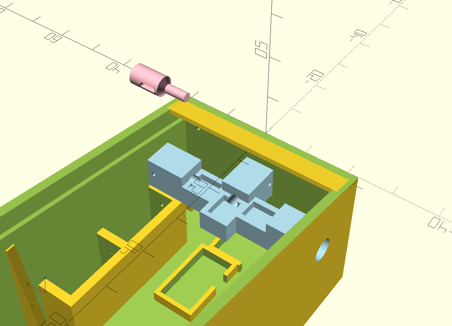
That is because the assembly that holds them is a separate part, press-fit and then welded (using a drop of resin and an UV laser pointer) in place. This picture shows the assembly in blue. It has three rectangular cut-outs where the microswitches live. These get actuated by the actual buttons, of which one is shown in pink above the case. There's a hole in the button assembly that interfaces with a slot in the button: I can put a brass rod through these to fix the button in place so it won't fall out but you can still press it.
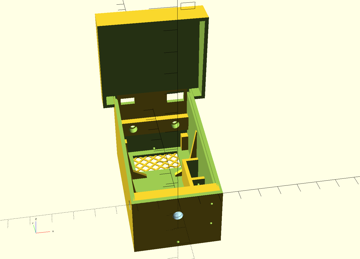
This is the body as seen from the front, with the backbox attached. The backbox is not too complicated; simply a box that contains the secondary LCD. It has holes for the power switch and the USB charging/programming interface, and it's kept in place with two screws which screw into two brass inserts in the main body. As the backbox stops the main LCD and PCB from sliding out, these two screws hold everything in place.

As I wrote earlier, it took some test prints to get to the end result. The final print ended up pretty nicely, though: printed in black resin, with most of it ready-to-assemble. I only had to put in the parts and hook everything up. One thing that was a bit harder was the plunger mechanism, as it was made out of brass rods that needed to be bent and soldered.

Here's a closeup of that plunger assembly. The plunger itself is located fairly high, so the brass rod it consists of is bent to connect with the actual plunger mechanics that are located more towards the bottom of the case. There, it connects to a second rod, which is held towards the back of the case with a spring (which is salvaged from a dead ballpoint pen). The rod ends in a little ball of solder (to make it a bit softer) which rests on the MLCC capacitor which serves as the sensor. Pulling on the plunger pulls back this rod and releasing it bangs it against the capacitor, where the piezoelectric effect does its thing and sends a signal back to the main PCB.
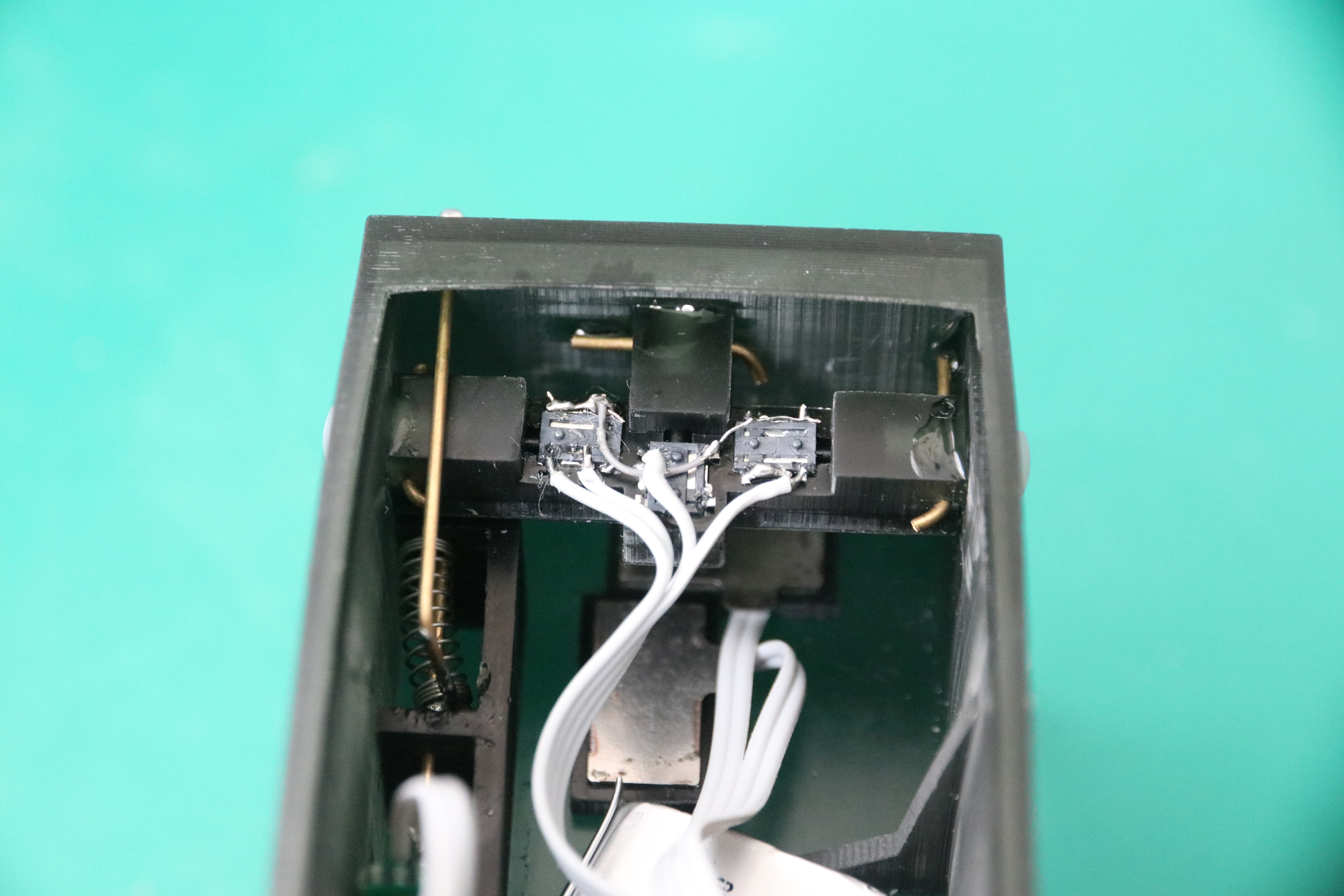
Here's another view. You can also see how the button assembly works: three little microswitches glued into their own little place; buttons held in place by brass rods threaded through the assembly. The entire assembly is held in place by friction fit and fixed in place by UV-cured resin.