Electronics
Now that I had a viable solution for some cheap whackable buttons, I still needed a way to read them out and indicate which button actually was hit first. The event I did this project for required at least 14 players, so 14 buttons. I wanted to have these buttons all connected over a single CAT5-cable. I also wanted a minimum of hardware in each button, to cut down on cost.
Cat5-cable has 4 pairs of 2 wires in it, totaling 8 wires. Over these 8 wires, at
least 14 buttons and 14 LEDs should be connected, totaling 28 devices. Because
I wanted to make the hardware as universally adaptable as possible, it should
also be possible to control each LED directly, and detect a press of each button
independent of what other buttons were pressed. This proved a bit of a problem...
connecting everything in a standard button/led matrix would take at least 11 wires,
Charlieplexing is a
possibility but I wasn't sure if I could control the buttons without ghosting, and
analog ways (e.g. every button switching on a different resistance) seemed too
noise-prone. In the end, I went with a simple 4x4 matrix-setup where the lighting
of the LEDs and the reading of the buttons could be done separately because of
different electrical behaviours of the components. Allow me to explain by
showing the schematic of the buttons:
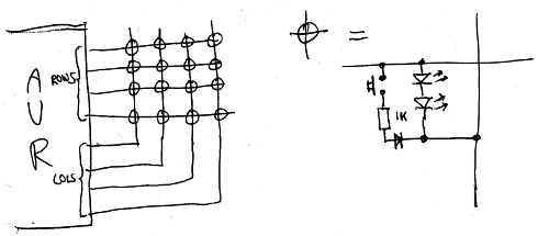
As you can see, the button/LED-combos themselves are switched in a standard 4x4 matrix,
yielding 16 button positions. Normally, the AVR scans the matrix for button-presses by
making low one of the column lines and enabling the pull-up on all the row lines.
When the button isn't pressed, a small current, limited by the fairly high resistance of
the AVRs pull-up-resistor, will run through the LEDs. Because the forward voltage of both
LEDs in series is about 4 volt, the AVR will still detect a 'high' on the row lines.
Now, when someone whacks the button, this situation will change. When the button is scanned, not only will the current run through the LEDs, but also through the button, resistor and diode. Because the forward voltage of the diode is about 0.7V and the resistance of the 1K resistor is negligable when compared to that of the pull-up-resistor, the voltage on the row line will be pulled to 0.7V and the AVR will detect a 'low' there, indicating the button has been pressed.
Now, the AVR will want to indicate it has detected a button-press by lighting the LEDs. It does this by again pulling low the column line and actively pulling high the row line. This'll make the LED light up fully, with the current through it limited by what the AVR can provide. When the button is pressed, some current will also run through the 1K resistor, but because the AVRs current isn't limited by the internal pull-up anymore, this doesn't affect the LED much.
Aside from just lighting the button requested, I also wanted to make a specific noise for each button. Rather than building in extra hardware to do that, I decided on connecting the AVR to a PC. That way, I could configure the actions of the buttons by just hacking a script on the PC instead of reprogramming the AVRs flash. I used vUSB to emulate a virtual keyboard: every time a button is pressed, the corresponding hexadecimal digit is 'typed' on the virtual keyboard, followed by an enter. This makes it trivial to whip up a bash script interpreting the button presses.
vUSB has some hardware requirements to interface to the USB-port of a PC, and I
integrated that in my schematic, making the complete schematic look like this:
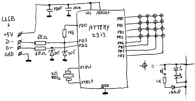
As you can see, I feed the AVR off 5 volt and use two zeners to limit the voltage on the
USB lines. The other alternative, running the AVR off 3.3V, doesn't work because the AVR
wouldn't be able to light the LEDs with that voltage.