Current source
Normally, when you want to run a LED, you'd put a series resistor on it and connect it all to a voltage source. If you want to vary its intensity, put a transistor in series and let a microcontroller do some PWM-work on it. Here, that would pose a problem: with a 3W RGB-led running at voltages around 2.5V, this solution would consume another 3W in the series resistors. Apart from that being a waste of energy, in this setting the heat would become another problem: All the electronics will be stuffed into a cramped space, with heat-insulating material like glass and plastic surrounding it. 3W of extra energy could very well mean overheating and at the least a malfunctioning device.
So a linear power-hungry solution like series resistance wasn't an option. I had to go for a switching solution. After some experiments, a few thoughts and a bit of help from people on a Dutch forum I frequent, I decided to go for the following schematic:
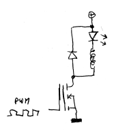
This looks weird, but basically is a standard buck-converter, but turned upside-down, so it'll generate the wanted voltage difference between the (+) and the cathode of the LED. This is useful for two reasons: first of all, it means I can use a N-channel mosfet easily. This type of mosfet usually is more efficient than the P-channel type I would need otherwise. The other reason is that the RGB-led is common-anode: I can't separate the anodes of the leds, so they have to be connected to a common rail.
My experience with buck-converters wasn't that exhaustive, and at first I figured that
the duty cycle would be linear with the PWM-value. After having built a test
circuit and seeing that the light intensity didn't react linear at all, I decided to look
a bit further. It seems that, in continuos mode, the PWM-value is linear with the
voltage on the output. That, in combination with the diode-like behaviour of an
LED, gives some weird results: when the output of the buck-converter is under the forward
voltage of the LED, the buck-converter works in discontinuous mode giving the whole
system a PWM-like behaviour. When it is over the forward voltage, the parasitic resistances
of all the components work as a current limiter. I made some quick and dirty measurements,
using some hacked code for an ATMega88 and a standard el-cheapo multimeter for
current-measures. The data I got looks, when put through gnuplot, looks like this:
(Horizontal: PWM duty cycle in %, vertical the current in mA)
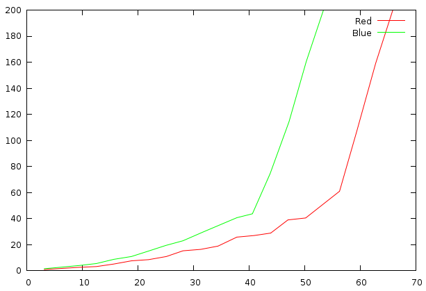
As you can see, the relation between the PWM value and the current running through
the LED isn't linear by a long shot, and if that wasn't enough, it's dependant on the
forward voltage of the led-chip in question too. I decided the only way to get a stable
current was to measure it and adjust the PWM-value based on that.
All in all, I ended up with this schematic: (click for larger)

As you can see, the boostconverter has a resistor added in series with the LED to measure
the current through it. There's no way to have the voltage over the resistor measured
in reference to the ground, so I had to take an AVR with multiple differential AD-inputs.
That's how I ended up using the 'tiny44. The current through the resistor is used by the
software to adjust the PWM-value, so all in all, the current through the LED is
configurable by the user. The other thing connected to the AVR is the
433MHz RF-receiver. I had to really decouple the power supply for the little thing: being
quite sensitive to RF-noise, it had huge problems functioning in the same environment as
the switched PSU and the buck-converter for the LEDs. The resistor and the capacitors
in this schematic work as a low-pass filter, which removes enough of the noise to make
the system workable.