Build, software
The build went easier than I thought, everything fitted just fine.
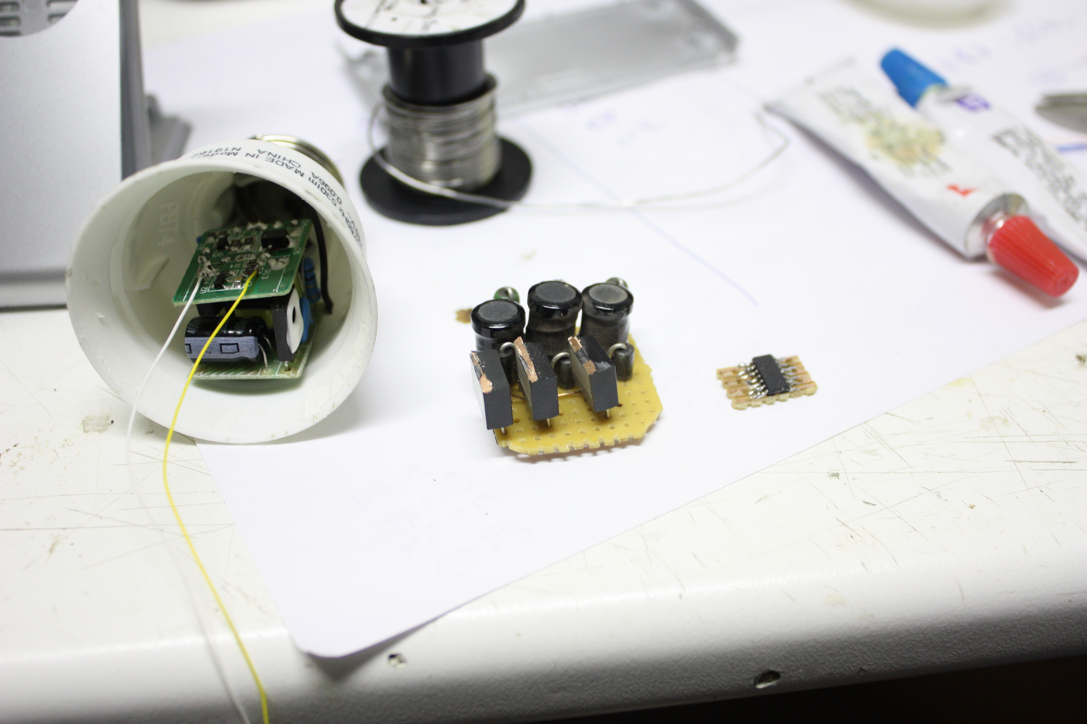
The PSU is built into the base of the lamp here. Next to it is the PCB with
the buck-converters and shunts etc, and next to that is the (tiny!) ATTiny44
on its little prototyping board.
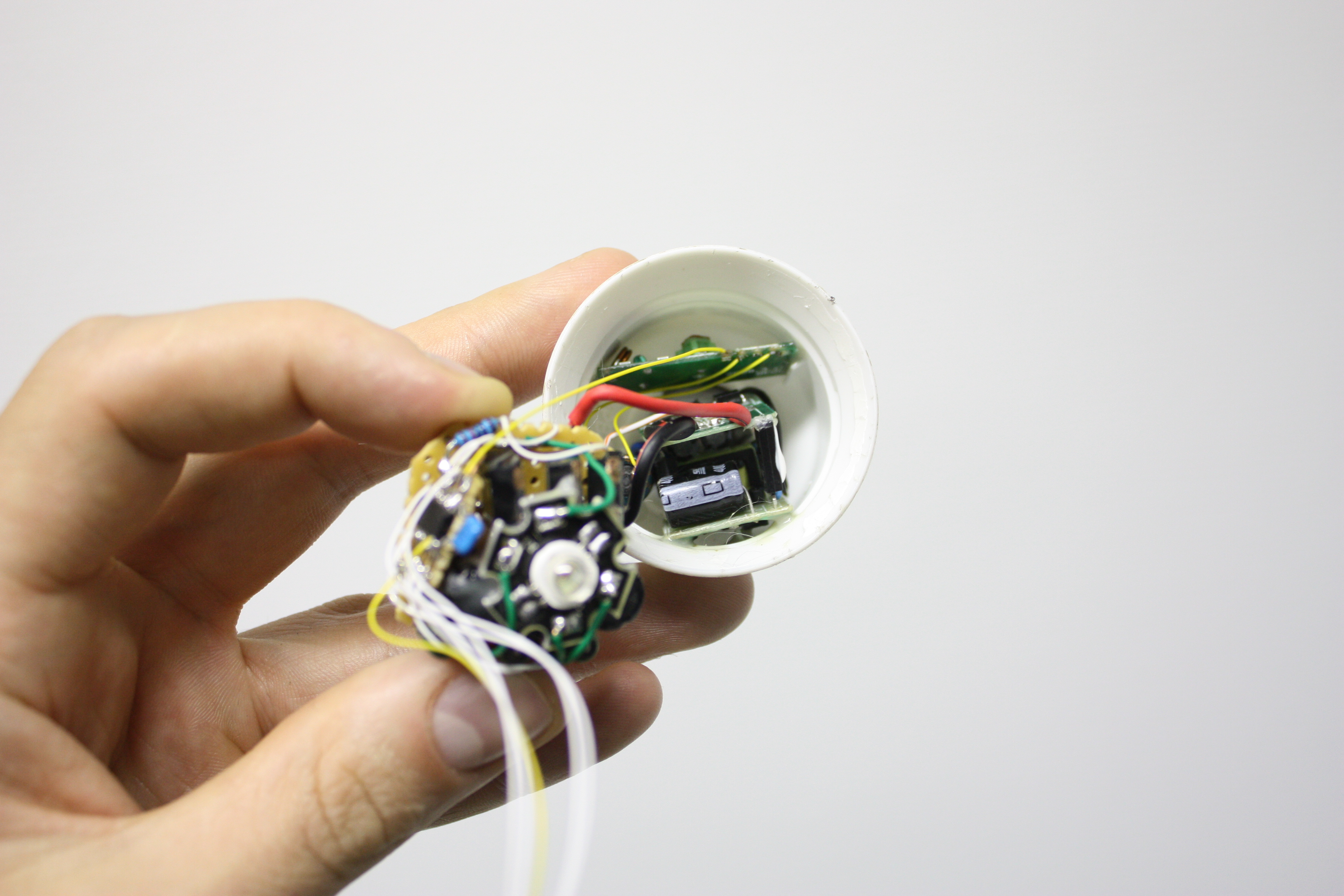
Here, the RGB-led uis glued on top of the boost-PCB and the RF-receiver
(without it's power decoupling here) is glued next to the PSU, which is glued
in place too. The two PCBs are quite close to eachother, so in the end product
I glued a bit of plastic between them for insulation.
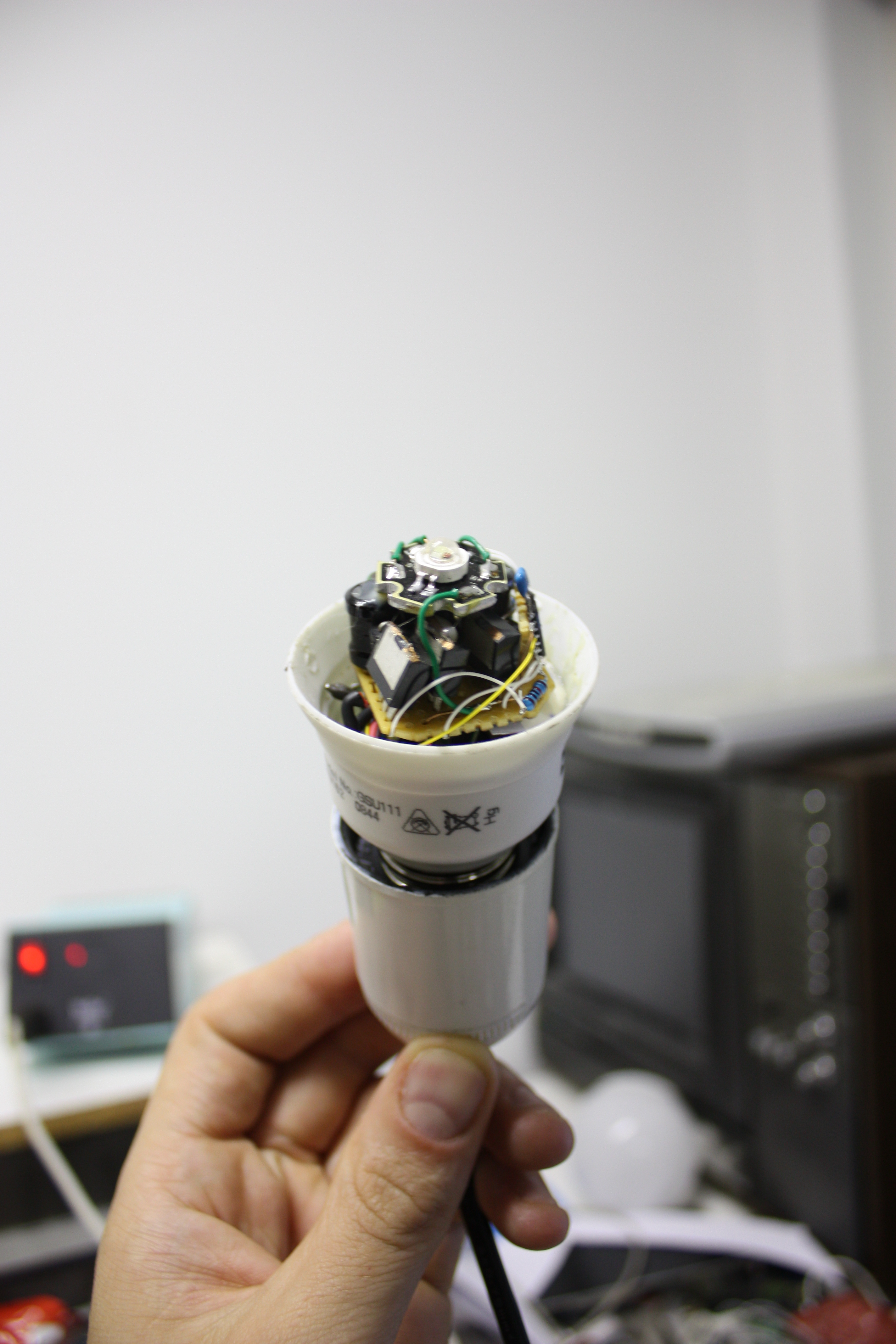
And this is the end result, without the glass bulb on. The design is nice
and compact enough not to protrude from the base too much.
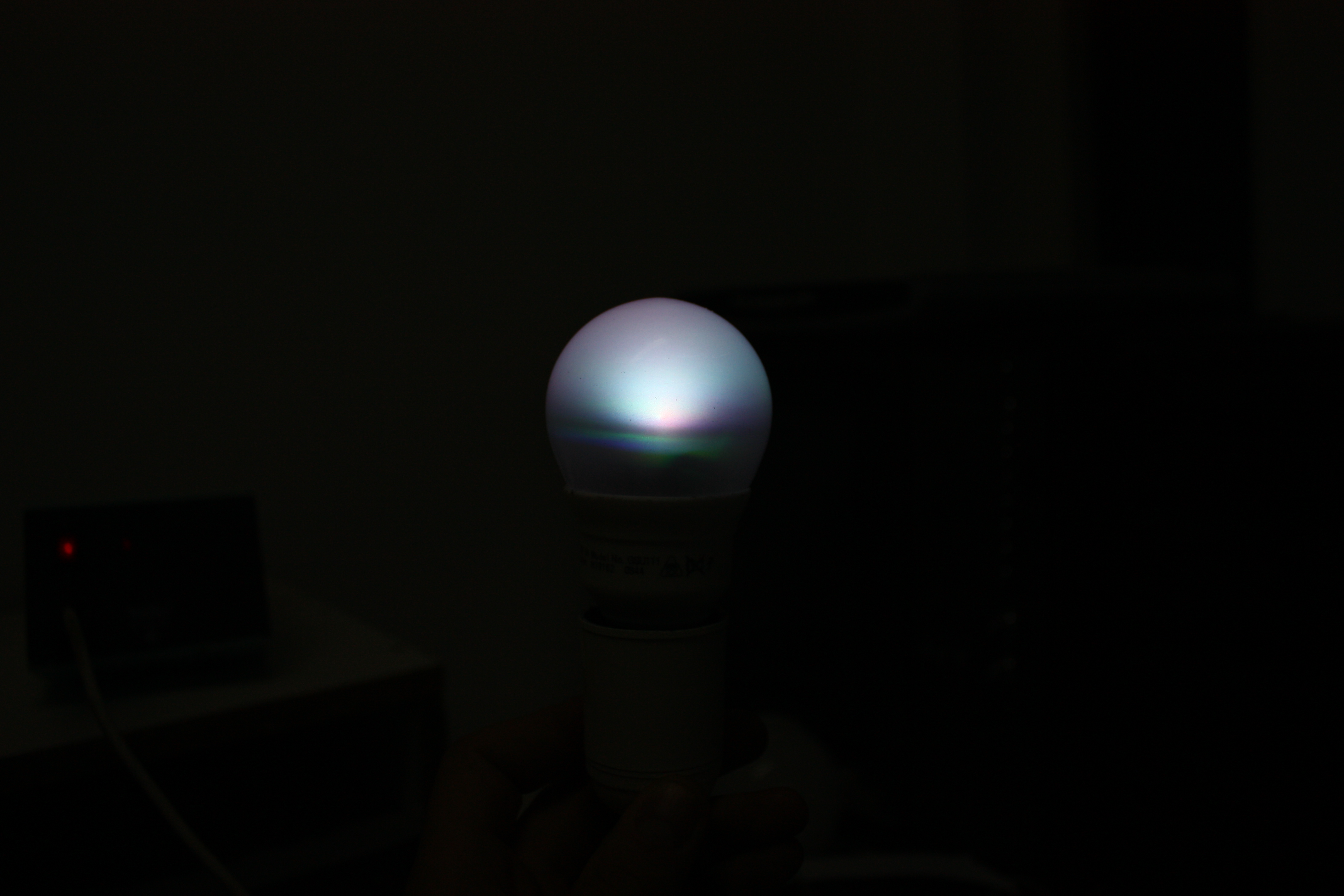
And this is how it lights up. The RGB-led itself already has the colors
quite close to eachother, and the frosted bulb acts as an extra diffuser, making
sure the colors are somewhat evenly mixed.
The software in the device isn't that extensive. The RGB-values for the LEDs get received on the 433MHz RF-module. That'll output the demodulated signal to a pin on the AVR. An interrupt on that pin triggers every time the signal changes, and the decoding routine will measure the time between this events. Long story short: pulses with a wrong length get thrown out and the rest gets decoded into a command to set the R- G- or B-value. On recieval of these commands, the value itself gets stored in memory.
The microcontroller also runs a loop which continually runs AD-conversions on all the channels. Because the buck-converters output a lot of noise and, especially in the lower intensities, the measurement at a single point isn't really indicative for the current that runs. That's why multiple measurements are taken and the current is adjusted according to a majority-vote scheme. Apart from the currents, the internal temperature of the AVR is measured too. If that gets too high, it probably indicates that something is wrong and the LEDs or the SMPS gets too hot, so it will then shut everything down to cool down.
I decided that I wanted to see how the schematic with the small SMPS held up to the original graph I made, so I decided to adjust the firmware a bit so the device would record the PWM-value vs the current to its EEPROM. This is what I ended up with. Horizontal is the PWM-value (512 = 100%), vertical is the current (65535, which is where red tops out, is about 1.1A. Yes, the red led ran above its specs here I guess.)
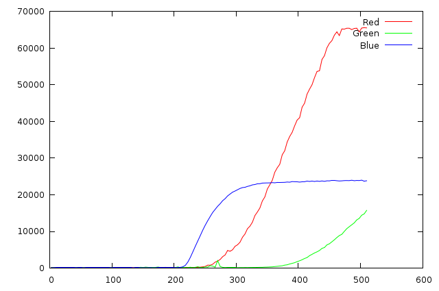
As you can see, the red and green LED get held up by the fact that there's a bit too much loss in the shunt resistor, mosfets, coil etc, but they both can reach the 300mA-level needed for a good amount of light.
As usual, the software is licensed under the GPLv3 (no BSD, sorry) and is downloadoadable here.