Results
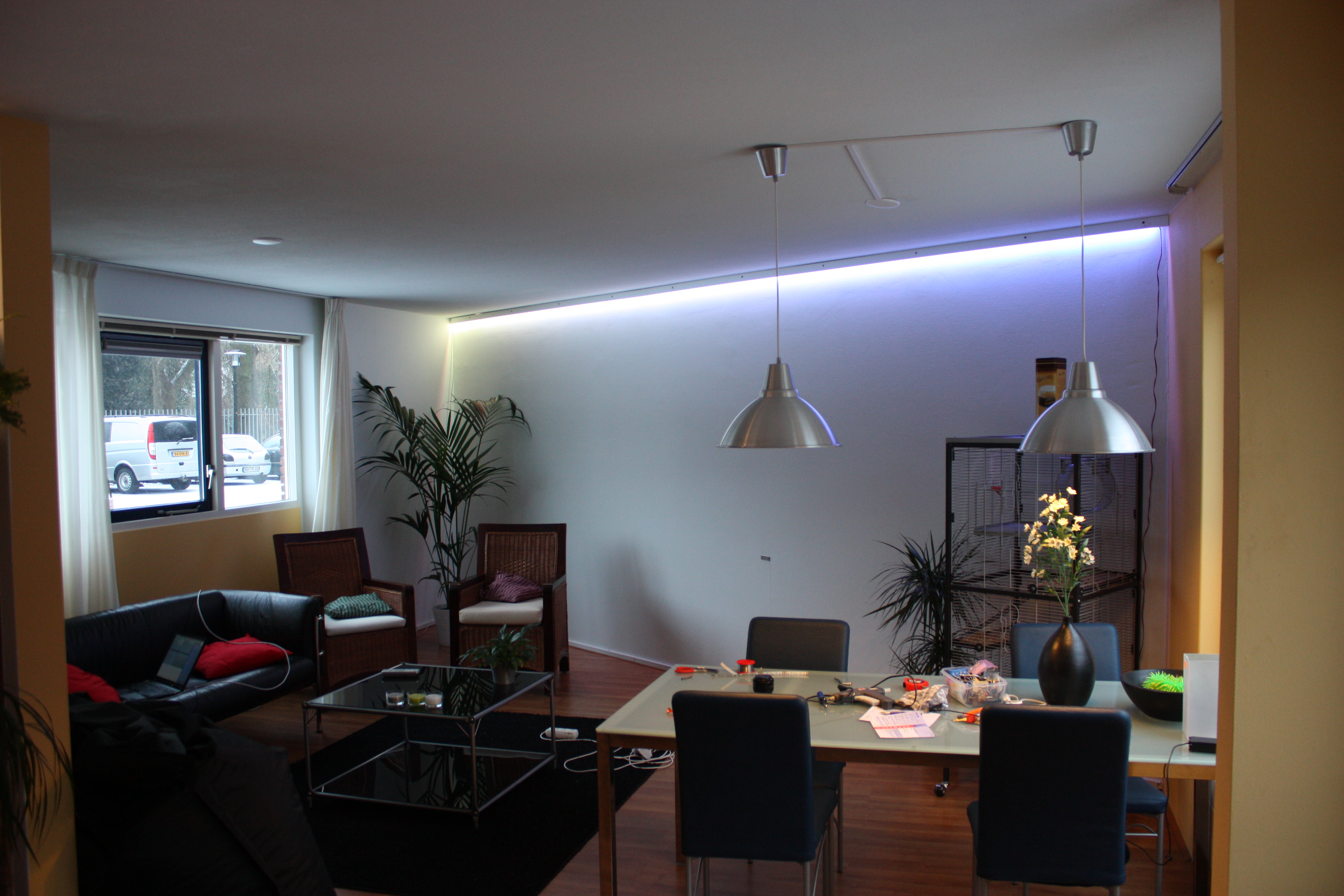
The LEDs power on all-white until they are told to do otherwise. This is just after
hanging them up: you can still see the holes the screws are in if you click on the image.
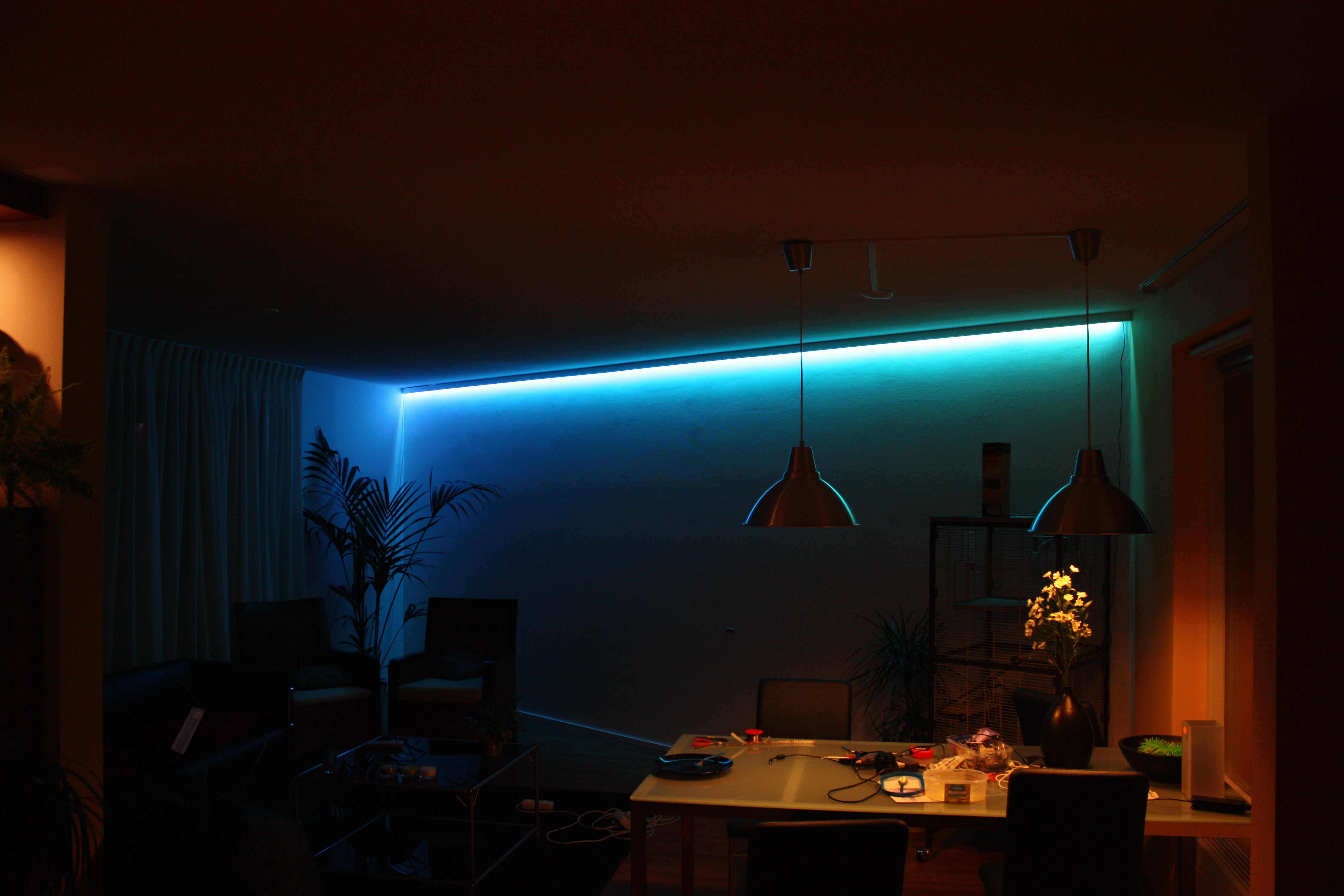
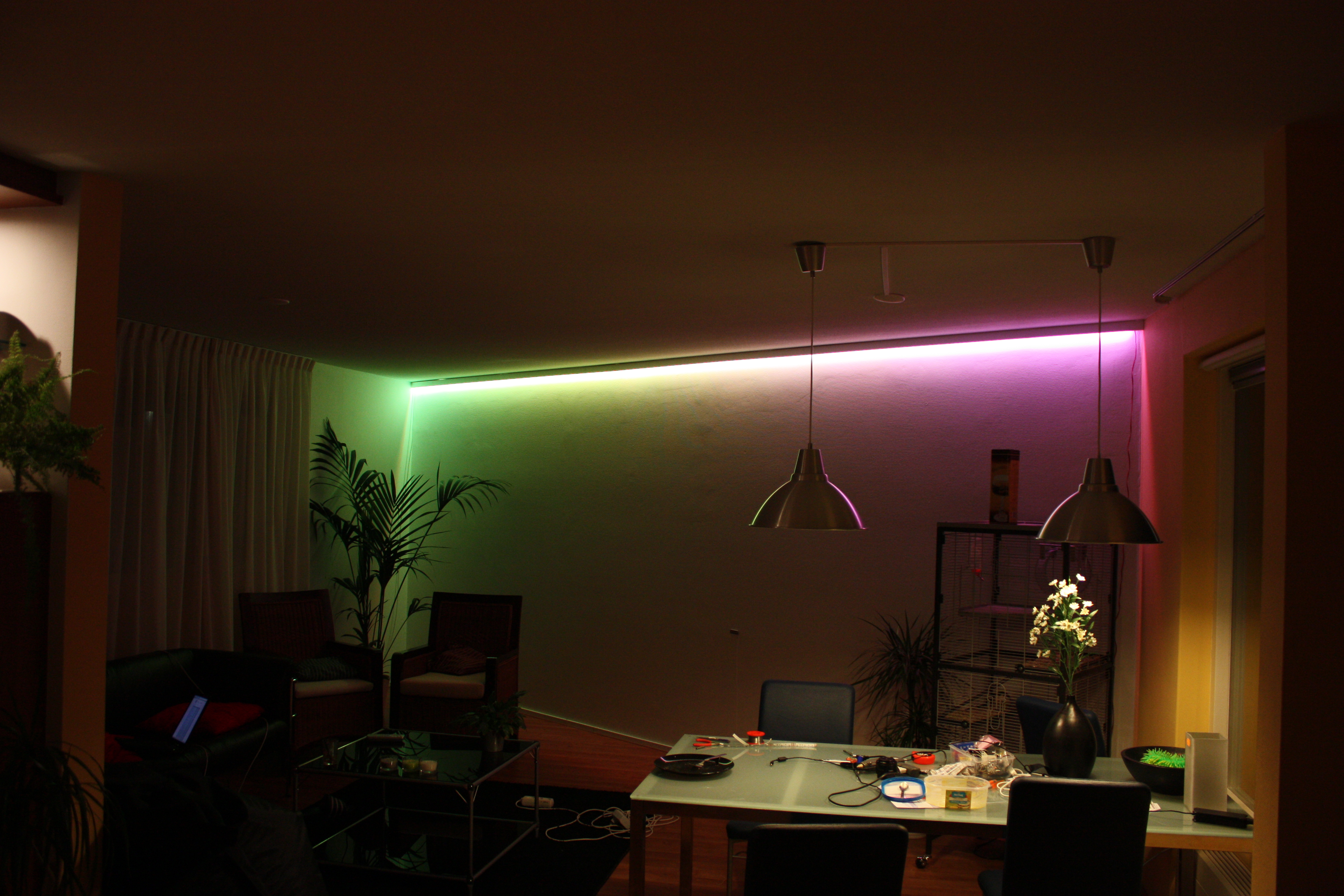
With colors. When it's dark outside, the effect is even prettier.
I made a quick-n-diry movie of some possible color effects, to demonstrate the
hardware. The movie unfortunately is a bit over-exposed, but the effect
should be clear.
original
The firmware, for what it's worth, and the PCB-design are licensed under the GPLv3, as usual, and can be downloaded here. There's a little demo-program for the PC included too. I still need to research some more effects: for example, having my very own automatic sunrise oughtto be a nice thing to have when I'm sleepily having my breakfast in the dark winter times.
« Prev 5
20 commentsGiovanni: The power is a nice fat industrial regulated 12V power supply. The power goes over a length of thick speaker cable to all the modules. The modules are linked in parallel to the RS422-line: they know their position because the A0-A2-lines on the modules are wired differently. There indeed is an USB-to-RS422-thingy on the PC side, consisting of a MAX422 and an FT232-chip.
I had a couple questions: How did you power the entire thing? A simple 12V wall-wart or a regulated power supply? How is power and data wires distributed to the boards? One of your pictures show a header for each module, but I wasn\'t sure how that works if you daisy chained the modules together I\'m assuming you have a small pcb board connected to your pc that converts between rs232 and 485? Thanks for sharing your work!
The addressing lines basically set the address of the module, in binary. There are 3 of them. Address 0 = all 3 lines pulled to gnd, address 1 = adr0 floating, the rest grounded; adress 2 = adr1 floating, the rest grounden; adr3 = adr0&adr1 floating, etc.
The only thing i\'m not clear on is how you us the addressing lines, any chance of some further info?
Excellent project, one of my friend is looking for exactly this type of thing to illuminate the wall behind a new book case, going to build one myself for some nice mood lighting.
Mosman: Any logic level N-type MosFET will do, if it can handle the currents involved (which are <1A here). In my setup, the MosFETS I chose are actually major overkill, but they were cheap.
What are the specs or reasonable ranges for the Mosfets you are using? I\'ve been trying to find the correct parts to duplicate your project, but have been unable to find the ones you have pictured.
Awesome! I\'m sure I will do something like this soon for my dorm room. I always wake up in a much better mood when I do it by the rising sunlight, so that sunrise idea is worth trying!
Great job, and amazing effect. It\'s a pity we don\'t get to see \"ready-made\" kits that allow \"non-electronic\" people to simple buy and assemble this at home.
Your tinkerings and creations always make me jealous :P Good work.
How about hooking the strip as a visualizer to the music player ;P
It would be kinda neat to hook this all up to a network router which can run OpenWRT or such distribution so you could control the lighting from WiFi devices like a netbook or smartphone. The Linksys routers can be modified for serial I/O or even bit-banged SPI or I2C. If you go with a AT90USB* device, you could use a router with a built-in USB port so no hardware hacking of the router would be required.
It is possible to make this on all 4 Walls? And i can Controll each LED? With Bluetooth or so, was it perfect. Great work... Looks very nice.
Kyle: There are two rats inthere (and yes, they have all the room in the world there) and they don\'t seem to particularily mind the colors. Rats can\'t see that well anyway. Balu: Sorry, no idea what it is exactly: I don\'t have a brand or name or whatever, just the specs: 36 RGB-leds per meter, 5060 form factor with a 120 degrees angle of illumination, 9W/m. Hope you find them :)
Is that a chinchilla cage, whatever animal it is, does it enjoy the light show?
Which LED strip did you use? I\'m looking for good mixing and nice white strip for a while now.
Nice work Sprite_tm! But.. no Arduino? :)
Great work !!! i Just <3 it !!! :D :D :D
Awesome! Very nice design. I love the final effect. Might have to have a go at this myself :)
Back in the day, there was a project called \'vos pad\'... http://vosled.com/projects/projects The pics look like what I seem to remember. Been wanting to do that myself.