Design
A year later, I came across the syringes of paint again, and decided that they were too cool to leave sitting in my drawer: if I didn't want to have a PCB made for it, I'd just have to find another way to make a clock with it. I started thinking: the tiny traces that proved so problematic were basically just resistors: why not take some real resistors and put a layer of paint over these? If anything it'd prove the concept that a display like that would be usable for a clock, and probably would give a bit more insight in what it would take to make a good display in other situations.
First, I needed to see what resistor value I had to have: that would determine the
amount of heat generated in it. Too much and I'd burn up the resistor, too little
and the paint wouldn't show.

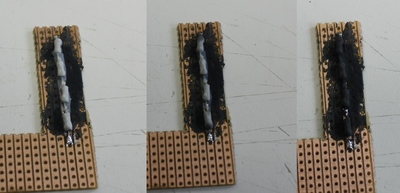
My first try was spot on: this setup uses about 500mW per resistor for a few
seconds. The power still was applied manually by touching the resistors
with two probes connected to a power supply, just before snapping the first image. The
second and third image are made after 30 and 60 seconds.
Ofcourse, manually applying power every minute isn't feasible: for the clock I had to
automate the process. Luckily, programmatically applying power to 23 sets of resistors
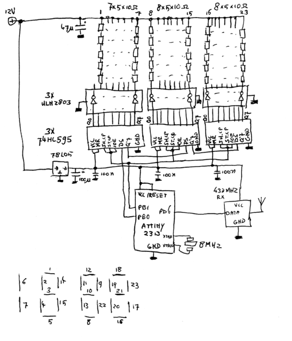
isn't really hard. I came up with this schematic to do it:

The circuit is fairly straightforward: an ATTiny2313 microcontroller shifts
23 bits into the 74HC595 shiftregisters. These bits are then fed into the ULN2803s
darlington drivers, which output a signal with enough oompf to make the 5x10ohm
resistors heat up a bit. That's all that is needed to light up a segment: the resistors
are painted with the thermochromatic paint which will then turn white until the
resistors have cooled down enough. (Btw: the schematic could be even simpler by
adding a diode to each segment and putting them in a matrix, but the idea of
having two chips per 7-segment-digit seemed aestethically better.)
The schematic also incorporates a 433MHz receiver. This is used to set the time: I have a 433MHz transmitter connected to my PC which I use for other purposes. I hacked an entry in cron which signals the clock at the top of every hour. This sounds complicated, but actually is one of the more simple approaches: due to the slowness of the display, a standard 'minute++/hour++'-buttonset wouldn't work. Moreover, the cystal running the show is not accurate enough to keep the time stable over the course of months, so automatically syncing the clock to something is preferred anyway.