How?
There are multiple ways to design a DC-DC-converter: Smartly using
capacitors to 'stack' the voltage, generating AC to put into a transformer,
using coils, ... The design I settled on uses the third effect and basically
is a standard boost-converter. For you people who don't know yet how a
boost-converter works, here's a short explanation:
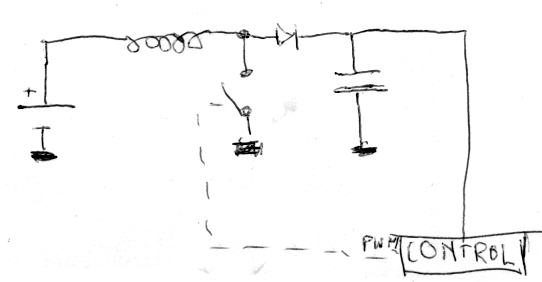
As soon as the switch closes, current goes and runs through the coil, which
in turn builds up a magnetic field. As soon as the switch turns off, the
magnetic field collapses, which has the effect of the coil seemingly wanting
to keep the current it had running at all time. There's no way for that
current through the switch anymore, so it only can go through the diode
and the capacitor. A capacitor increases the voltage over its connections when
a current runs through it, and this one is no different: the power at the
output increases. Now, if a load happens to be attached to the capacitor, it
will slowly discharge, and the voltage will lower again. To compensate that, the
control unit will close and open the switch many times a second, so the total
of current going into the capacitor will stay the same as the current going
out of it, thereby keeping the same voltage.
Usually, a dedicated chip is used as the PWM-controller which turns the switch on and off. A dedicated chip isn't a must, though, a microcontroller can handle the same task: all you need is an A/D-converter, a PWM-controller and some firmware to tie it all together. In such a configuration, the circuit can e.g. get 1.5V from a penlite and convert it to 5V to power another circuit. So I thought: Why then can't it power itself? The only problem you have is that the microcontroller doesn't work on 1.5V (duh, that was the problem in the first place) so we'll need a little something to kickstart it.