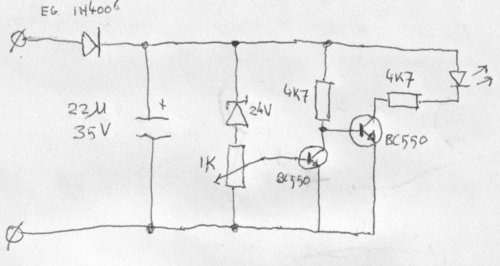
The schematic
An indicator is nice, but how to implement that? Because all the intelligence of the heat regulation happens inside the soldering iron, the station itself is just a big 230->24V-transformer and an on/off-switch. Running an extra wire to the soldering iron to sniff out its status wasn't an option. There is another way to get info about the actions of the Magnastat-switch, though.
The secondary windings of a transformer which primary windings are
connected to the mains power usually are seen as an ideal
voltage source which spits out a sinewave. A transformer never is completely
ideal, though: when it's loaded, the amplitude of the output signal lowers a
bit. The transformer inside the soldering station isn't an exception: the 24VAC
drops about a volt when the heating element of the iron is switched on. I decided
to create a circuit which could turn on a led when that happened.
While I can make microcontrollers and digital logic do exactly what I want, analog electronics never have been my forte and I usually get to a solution by just soldering extra parts to the circuit till it does what I want. In other words, I have no idea if this is an ideal solution for my problem, but hey, it works and only uses 9 parts.
How it works: The diode and the capacitor are used to convert the 24VAC into about 30VDC. The zener is used to put that voltage, minus 24V, over the potentiometer. That voltage amounts to about 6V when the heating element is on and a bit more when it's off. The potmeter is set to output a bit more than the .7V required to get the transistor in conduction when the heater is off, and a bit less then .7V when the heater is on; that way the voltage on the basis of the second transistor is high when the heater is on and low when the heater is off. That transistor drives a LED, which turns on only when the heater is on.