Building it
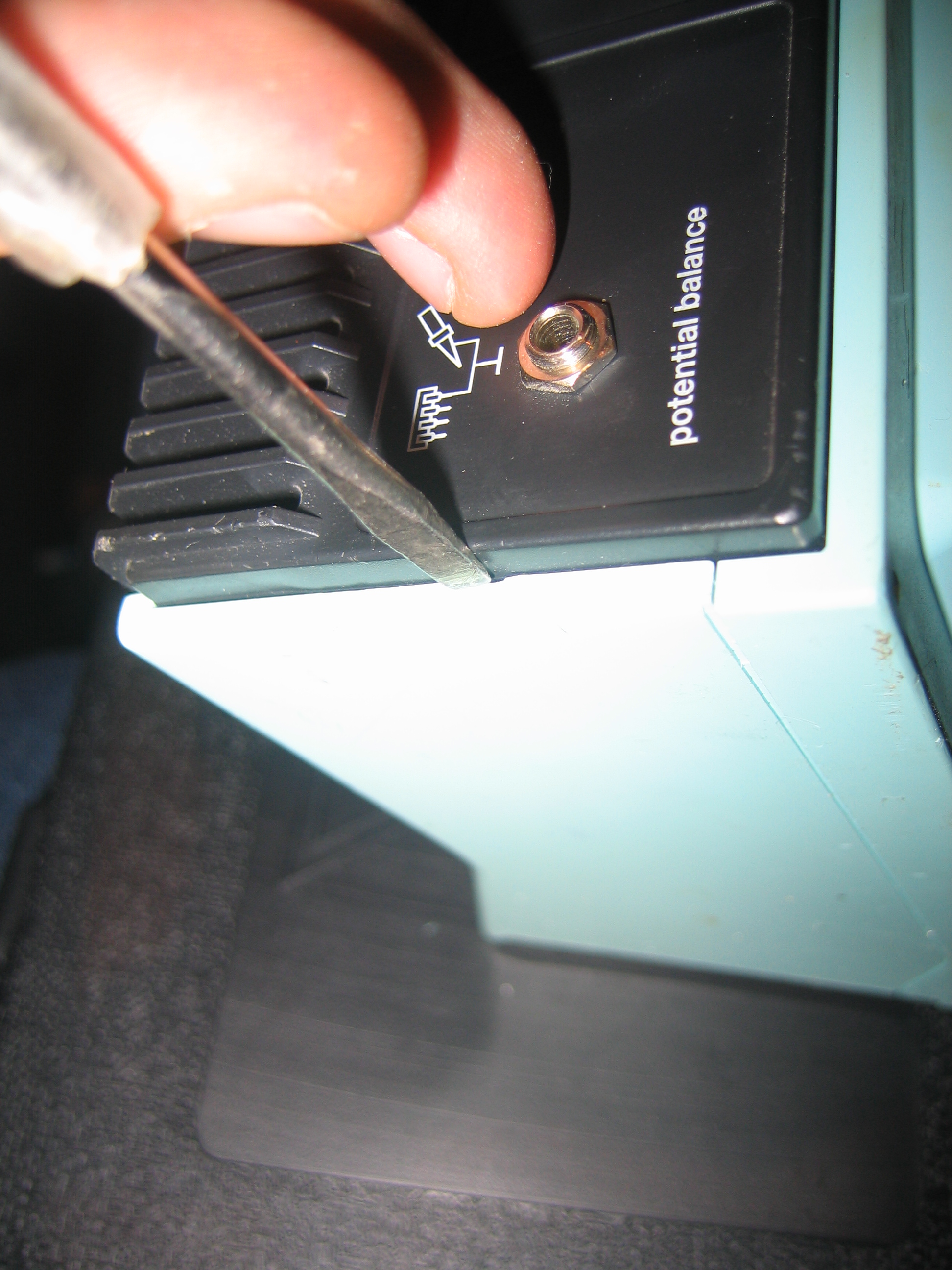
I started by opening the soldering stations base. It's kinda tricky because
there are no visible screws anywhere on this model, but if you know how it's a
breeze: On the backside of the box, between the sides and the black back the
power connector is fitted on, there are 2 small slits. Push a screwdriver
in there and push the blue upper housing upwards, and the thing will
automagically fall apart.
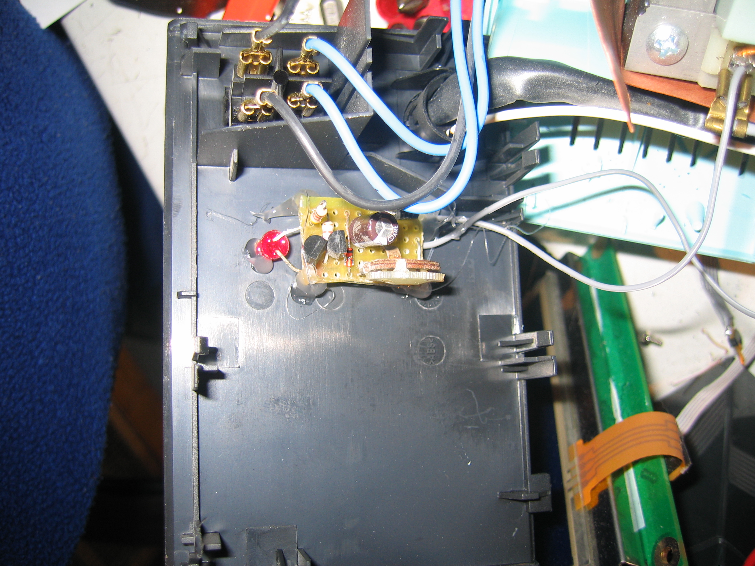
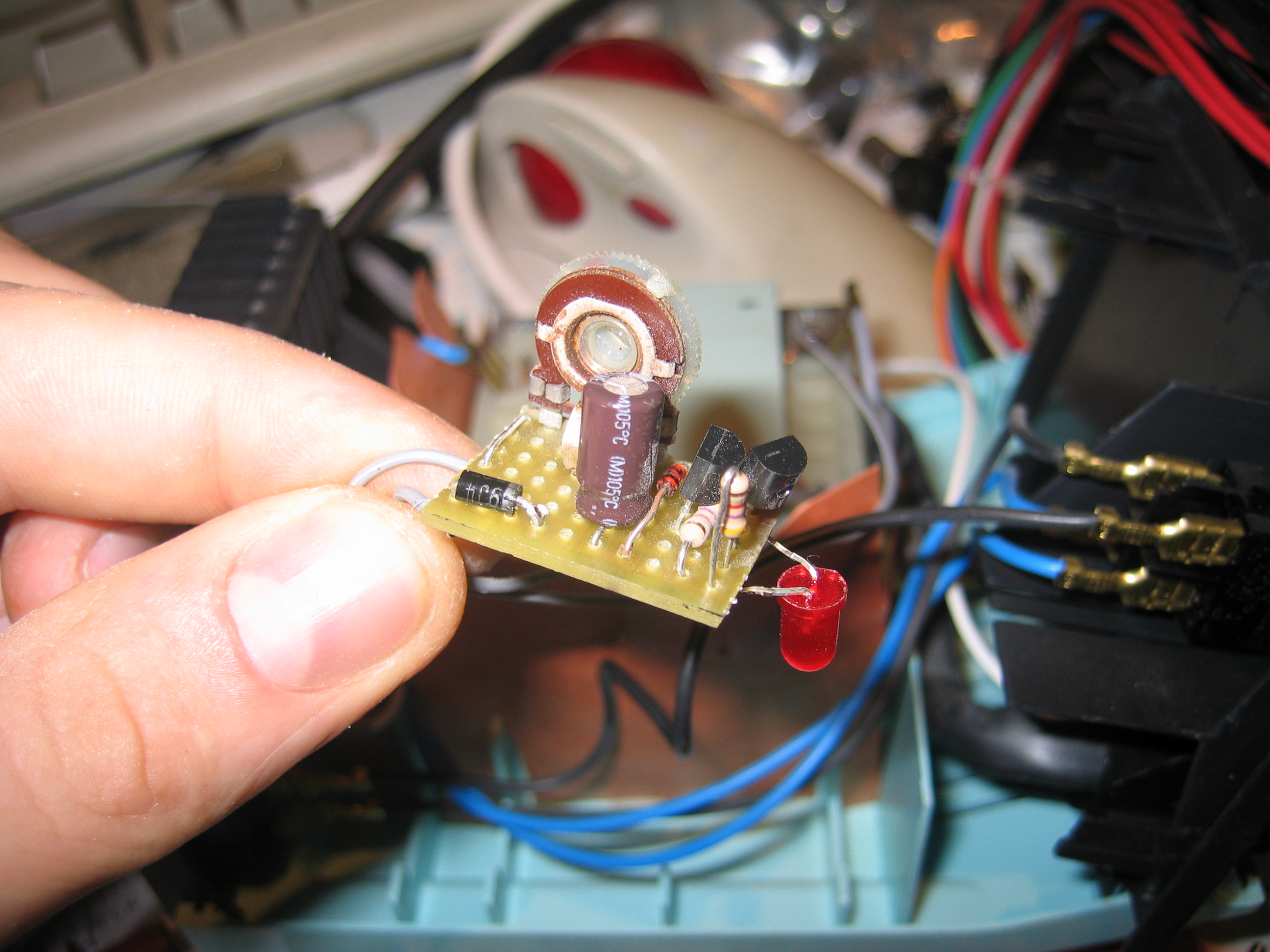
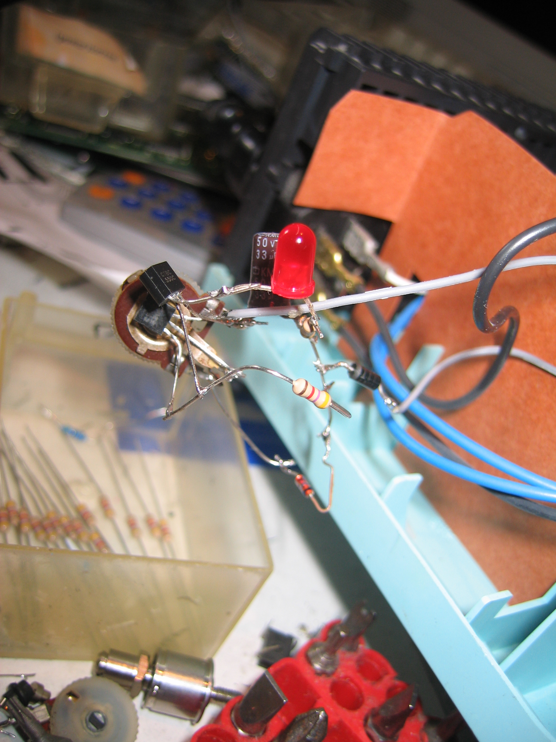
After getting all the kinks worked out of the PCB-less prototype,
I built the final circuit on a piece of prototyping PCB. The complete circuit
got quite small, so I wouldn't have problems putting it somewhere inside the
soldering station. Just one precaution: check your PCB before trying it out;
the 24V from the transformer really isn't forgiving to shorts or badly connected
parts. Be careful about adjusting the potmeter, too: if you turn it completely
towards the zener diode, the current through the zener might get too high and the
magic smoke will come out.
Calibrating the circuit is easy: move the potentiometer to ground turn on the (cool) soldering station. Now, wait till the soldering iron is hot and 'clicks' and turn the potmeter in the direction of the zener until the LED just goes off. You're done and if everything is OK, after a short while, the iron will have cooled enough to turn on its heating element and the LED should go on again.
I finally decided on fixing the circuit to its place with a quick-and-dirty
solution: I drilled a hole in the fromt plate for the led to peep out and fixed
the PCB with hot glue. The transformer in this model stays quite cool, so there's
no need to fear for softening of the glue.