Building it
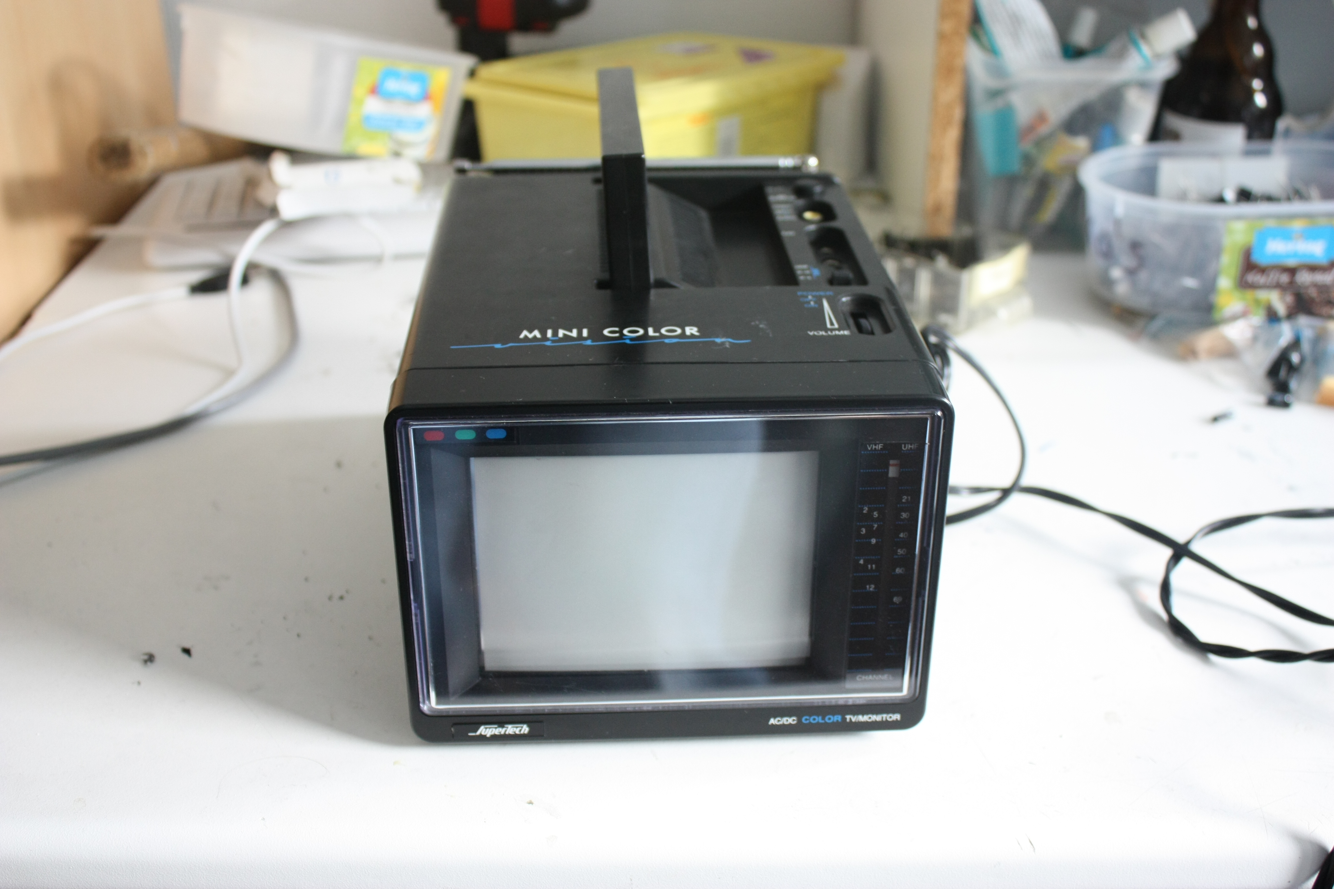
Of course, the main part of this project, next to the FPGA, is the CRT. I got myself
a nice portable color TV to grab it from. This one runs on 12V AC and actually still
worked when I got it.

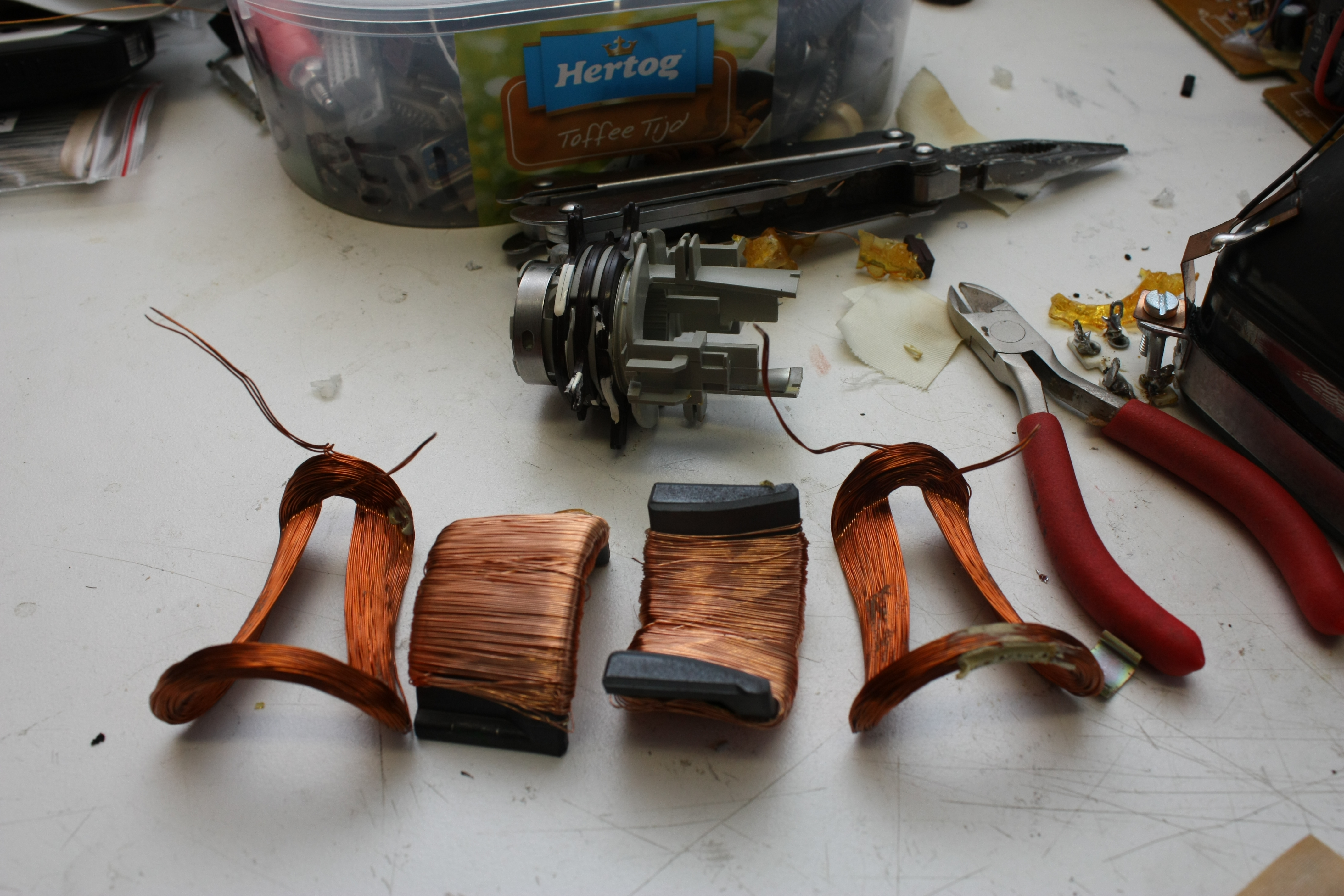
The CRT was a bit longer than I expected, but I could work around that. The TV had
three PCBs: the PCB on the back of the CRT, the HV and video PCB, and a PCB containing
the tuner and video inputs. I got rid of the last one. I modified the HV PCB a bit:
I made sure it always was on, independant of video input; I disconnected the deflection
coils and replaced them with small dummy inductors and I moved up the default HV flyback
frequency a bit so it wasn't so easy to hear.

First trial of the CRT... it doesn't look good. Seems at least one of the coils
has too much inductance; I decided to re-wind it.
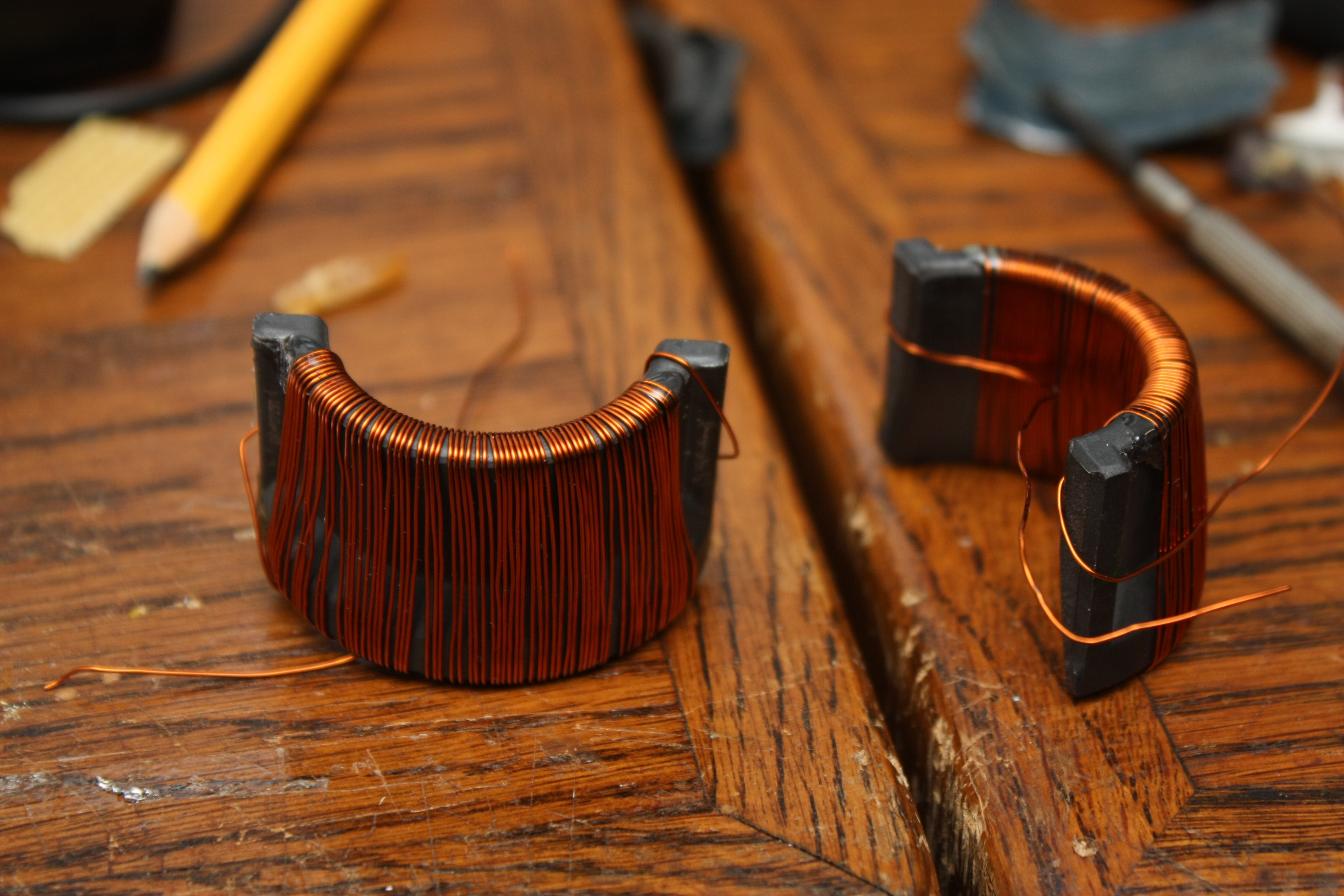
Much better.
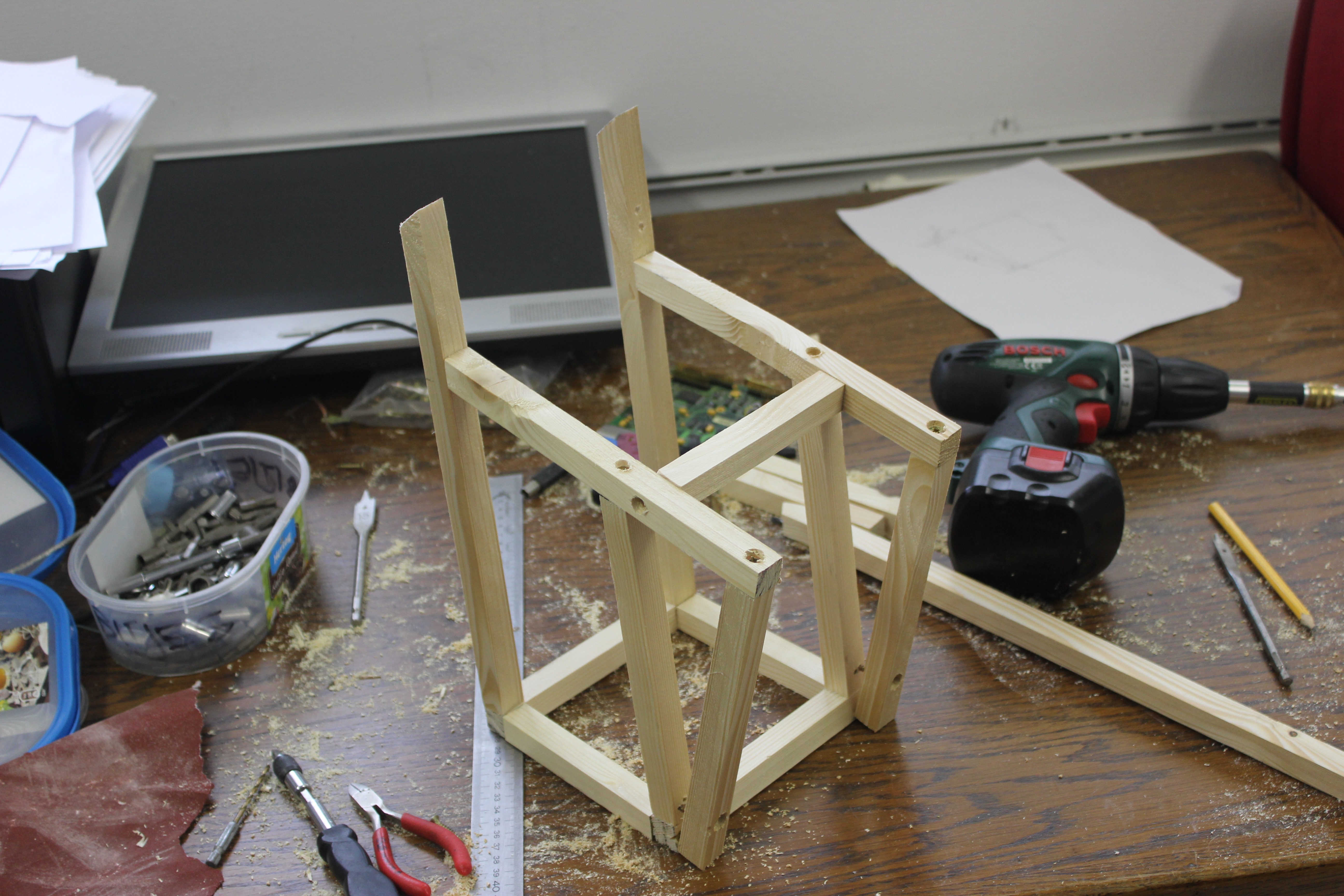
Ofcourse, I also needed a case for my handiwork... I could let it remain a bunch of
PCBs wired together, but I didn't feel like an unprotected CRT would be safe in my
projects bin. I am, however, not really good with wood work, so I decided I'd make
a frame first, so I could screw everything to that. I'd then put triplex panels over
it, so any mistake I would make would be invisible.
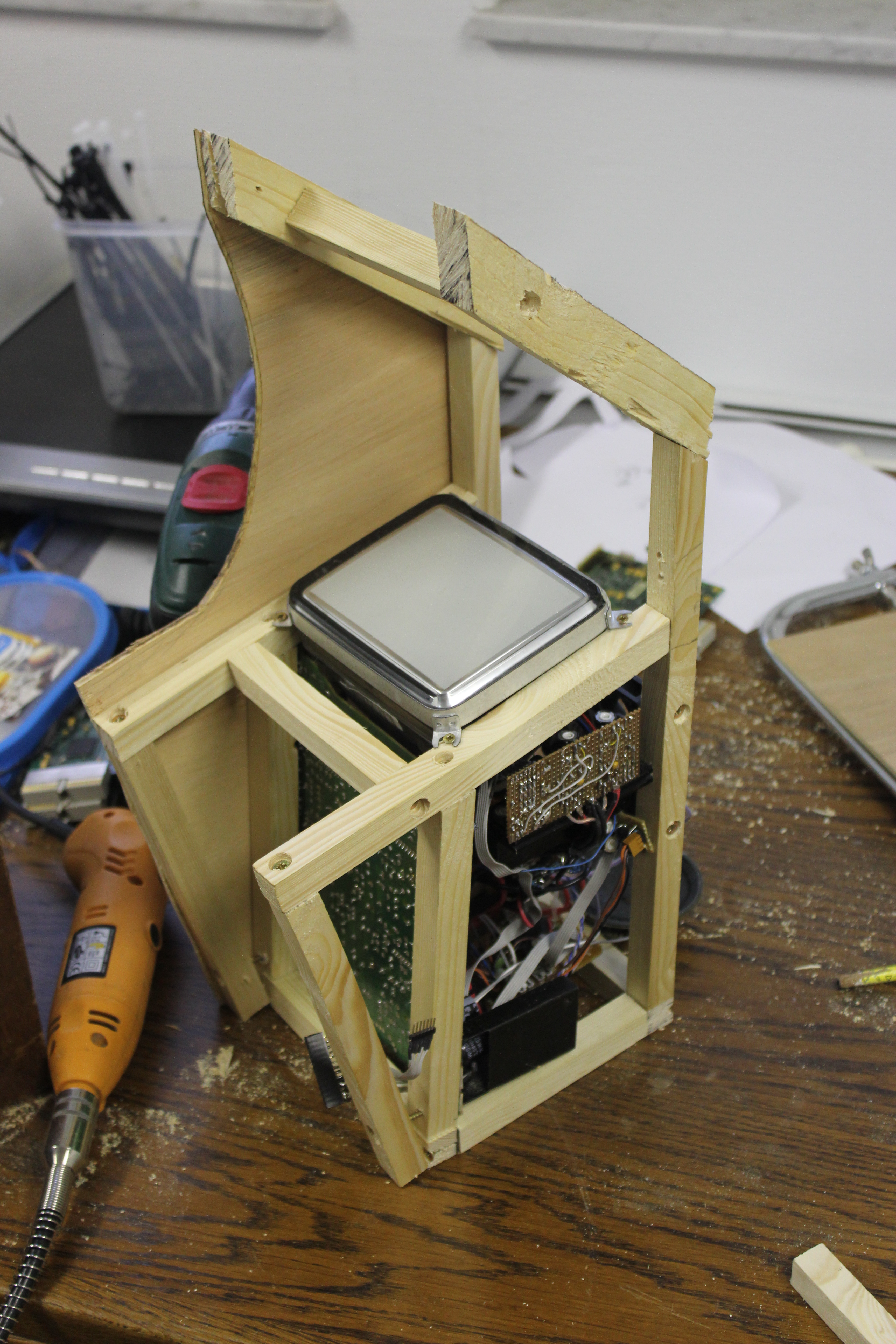
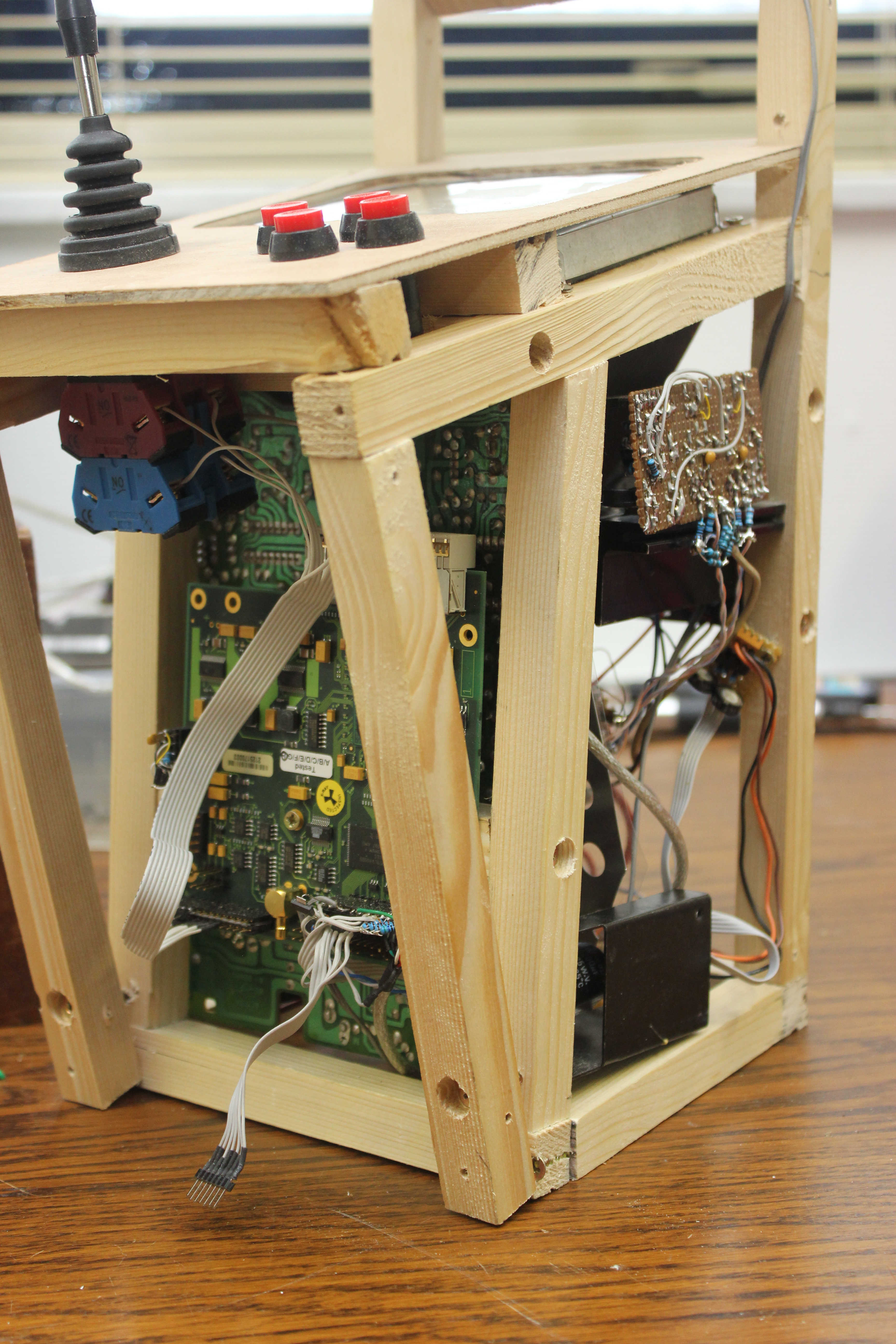
Here it is with the CRT and most of the electronics built in.
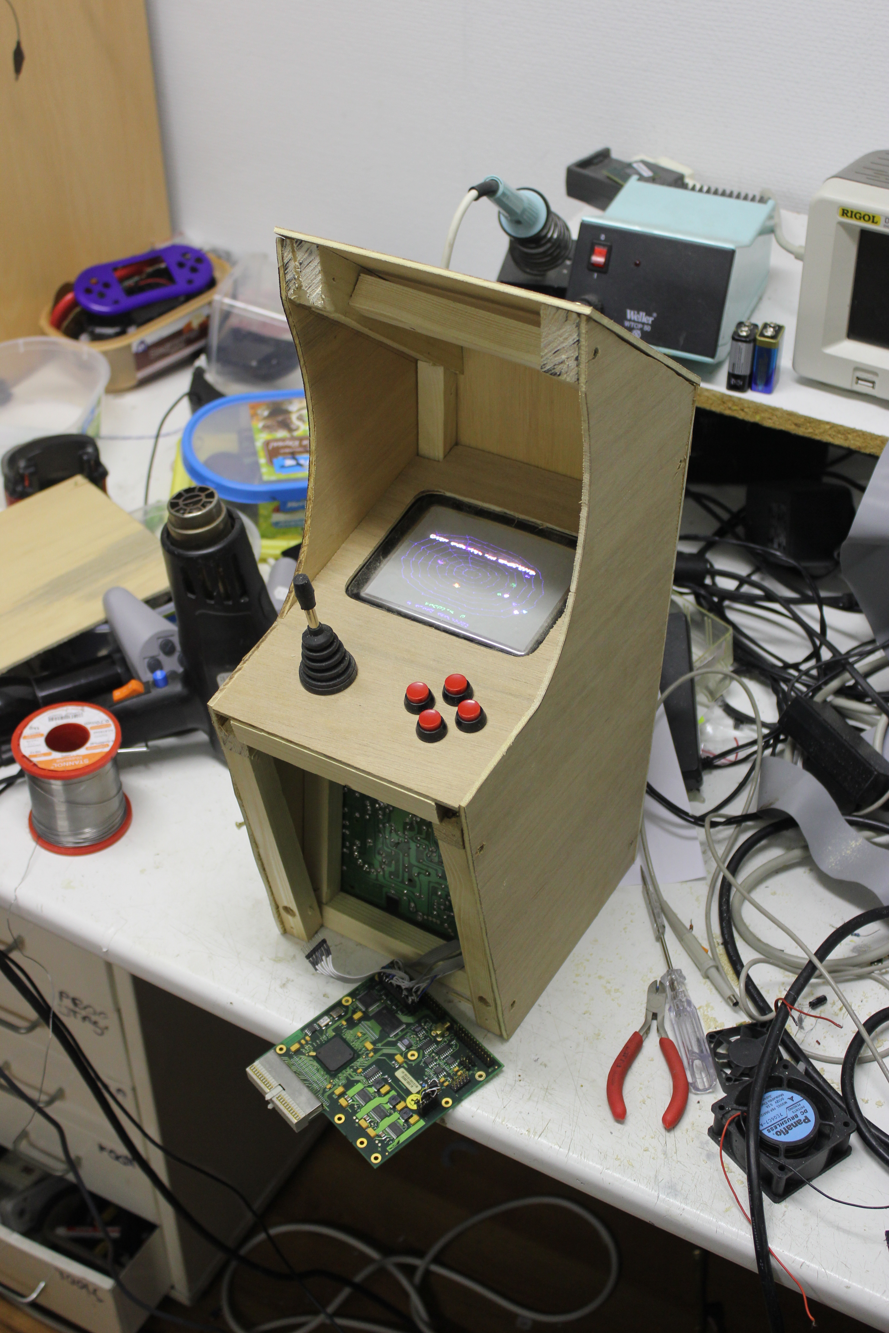
I also bought a small joystick and a few buttons to finish it. I later found out
the original Black Widow case has two joysticks instead of one plus fire buttons. Ah
well, this way is more universal, which is better if I decide to put in another game.
The FPGA board lies next to the open panel.
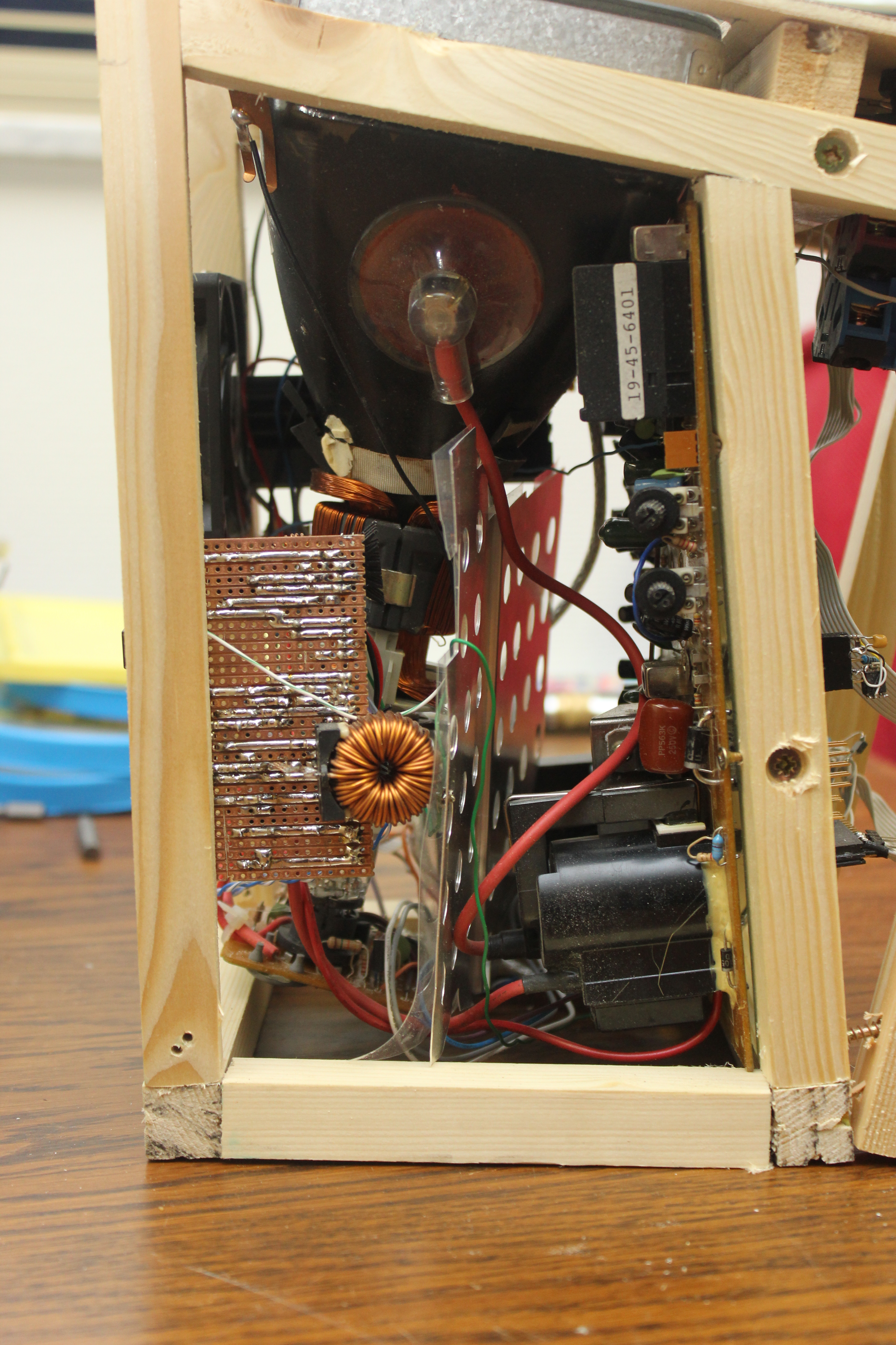
Side-view of the device without the panels. On the left, the DC-DC-converter
board, with the ginormous coil for the -15V power supply. On the other
side is the PCB that came with the portable TV; the flyback transformer is visible
on the right. In the middle a bit of aluminium: the flyback transformer spits out
a lot of magnetic interference and when that hits the deflection amps and
coils, the lines go all wobbly... this acts as a shield between the two. There's
transparant plastic on the shield so it doesn't accidentally short something.
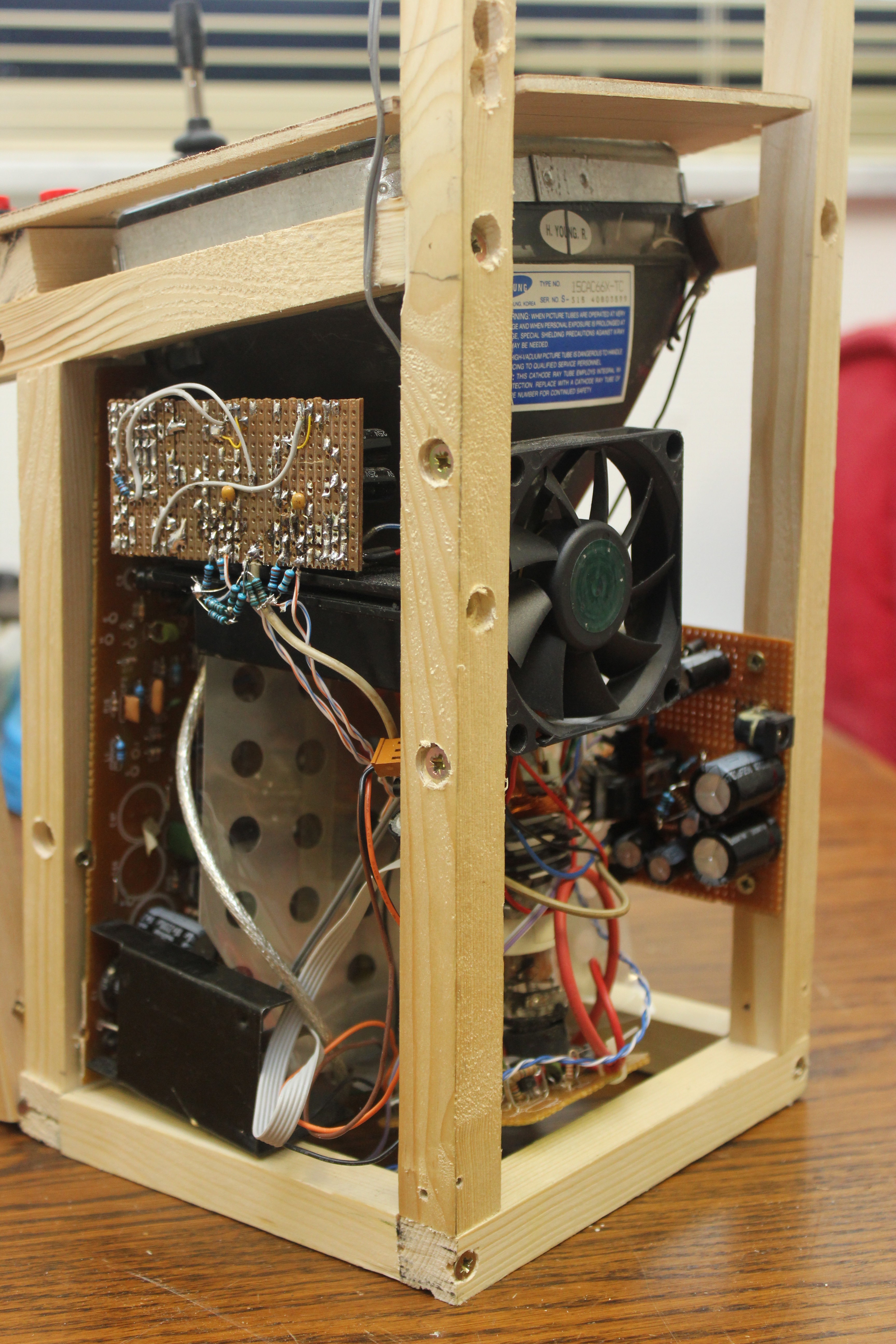
Back right view. You can see the fan I've installed to cool both deflection
amplifiers: they get quite hot. You can also see the top of the DC-DC-converter PCB:
lots of big capacitors and the connector for the 15V laptop PSU that acts as the power
supply to the machine.
And here's the front. You can see the buttons and the FPGA PCB. Behind the flatcable
to the buttons, you can spot the stand-alone jtag uploader thing.