Intro, disassembly
Since when I started Spritesmods.com, I have a tip jar on the right side of the screen. People who like my hacking enough can leave me some beer money there. Sometimes, people have something more interesting than beer money to tip, though.
A few months ago, I got a mail from an anonymous individual: would I be interested in receiving a nice LED-board? The board was made by the Italian company Solari Udine and was salvaged from being scrapped after a long life in some kind of transportation system. Ofcourse, I have done some things with a LED-board before, so naturally I accepted, moreover because the hardware was nothing to sneeze at: 224x48 pixels of dual-color LEDs, with an integrated industrial computer to control it all and three power supplies to deliver the needed amps into the LEDs and CPU.

When I received the hardware, I discovered the kind individual who sent it to me had
partially disassembled it so it would fit in the shipping box better. That gave me an
opportunity to first disassemble it a bit further and take a good look at the components:

This is the frame the LED-board is mounted to. You can see the two 5V PSUs in the
middle, which can provide 40A each into the LEDs. To the right, there's the smaller
PSU which provides power to the industrial PC, which is visible on the left of the
frame.
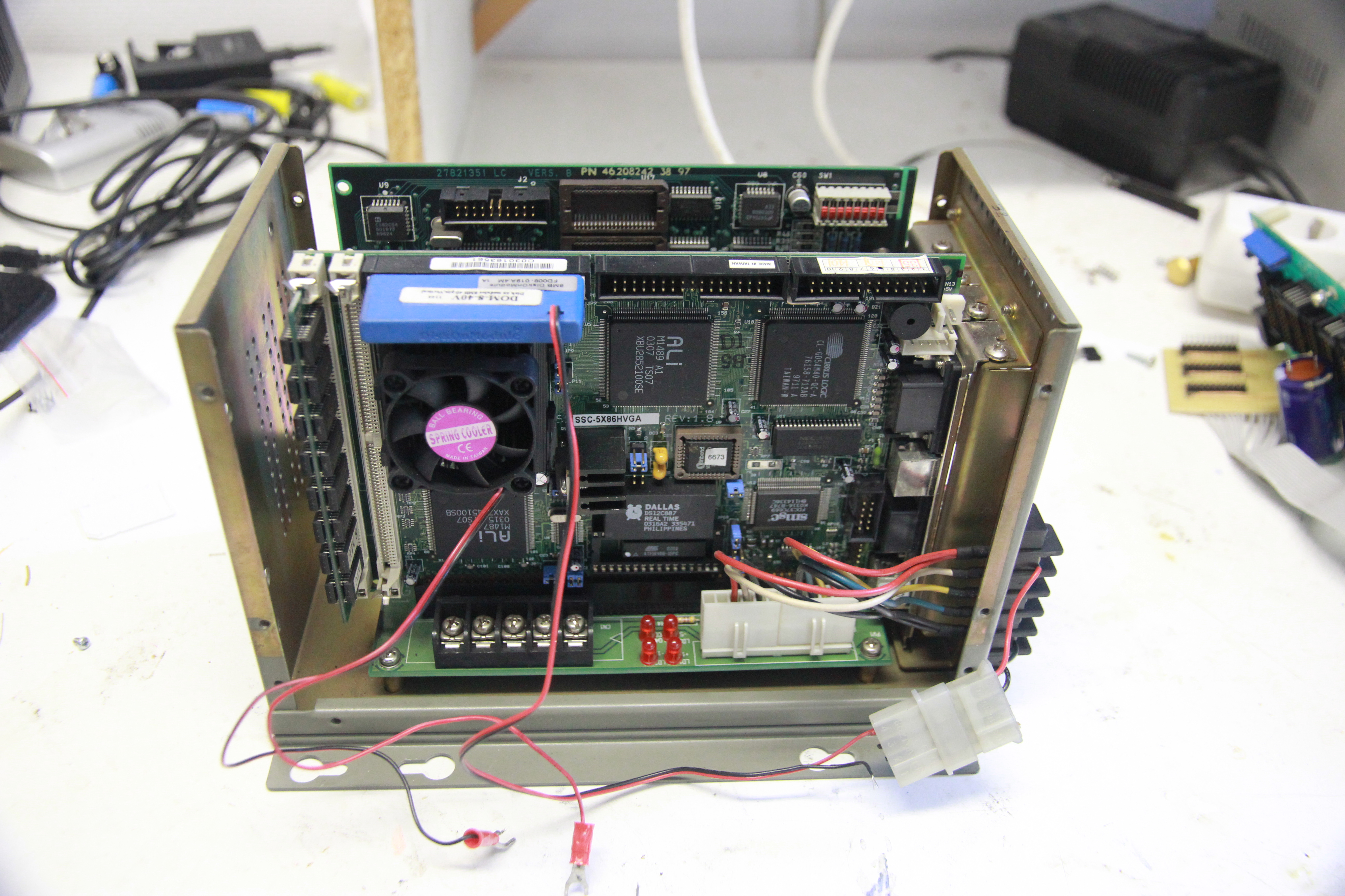
A better look at the industrial PC. It's basically a backplane based on the ISA-bus,
with the cards and the main CPU card plugged in as modules. There's four cards in there:
apart from the CPU-board there's a VGA-card, an 10MBit Ethernet-card and the LED-controller.
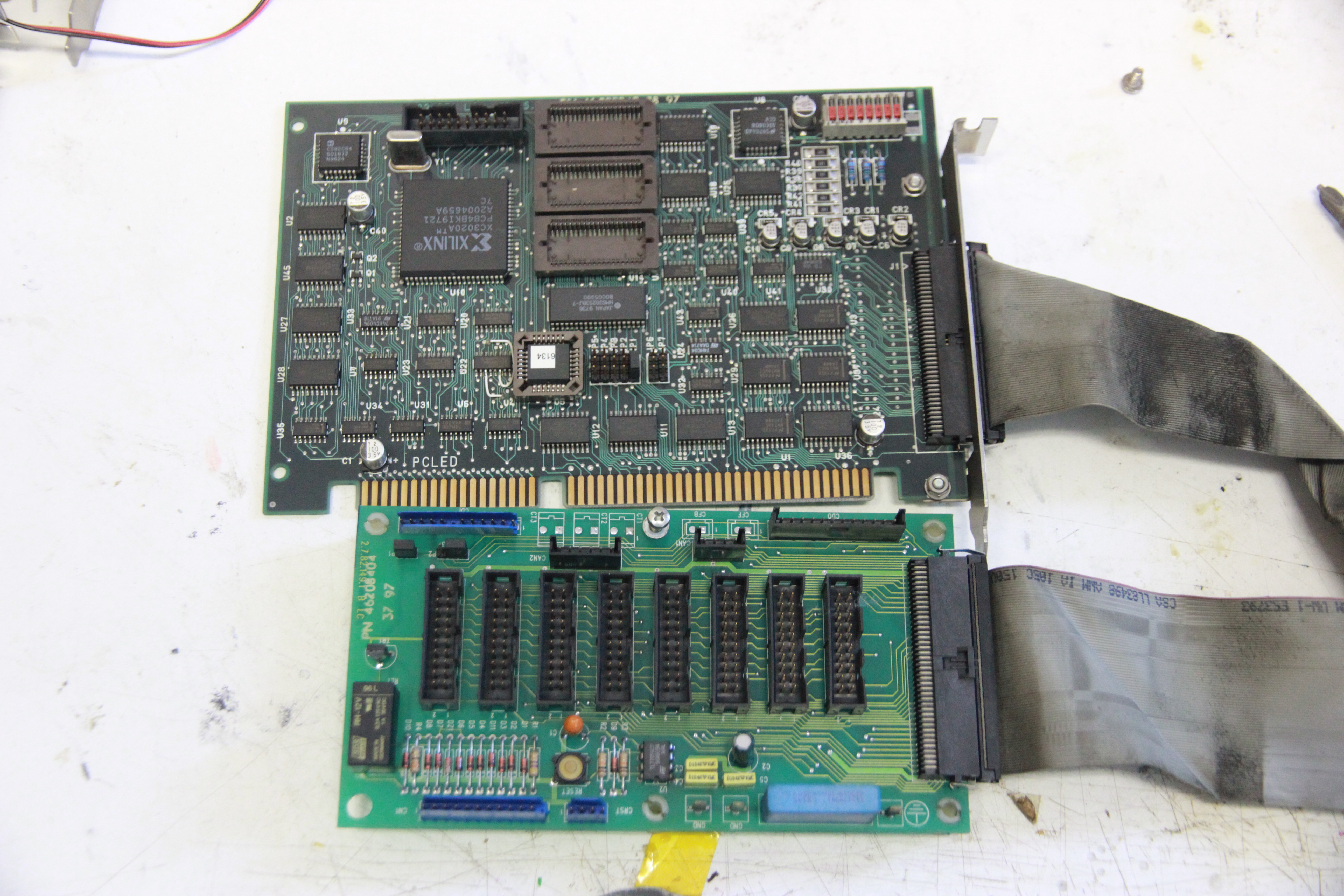
Closer look at the LED-controller card and the adapter PCB; the leads to the LED-modules get
plugged into that PCB. The controller card contains some discrete logic, a Xilinx
XC3020A FPGA and a bit of DRAM. The DRAM probably is used as a framebuffer for the LED
data, with the FPGA handling access from the ISA bus and signal generation for the LEDs.
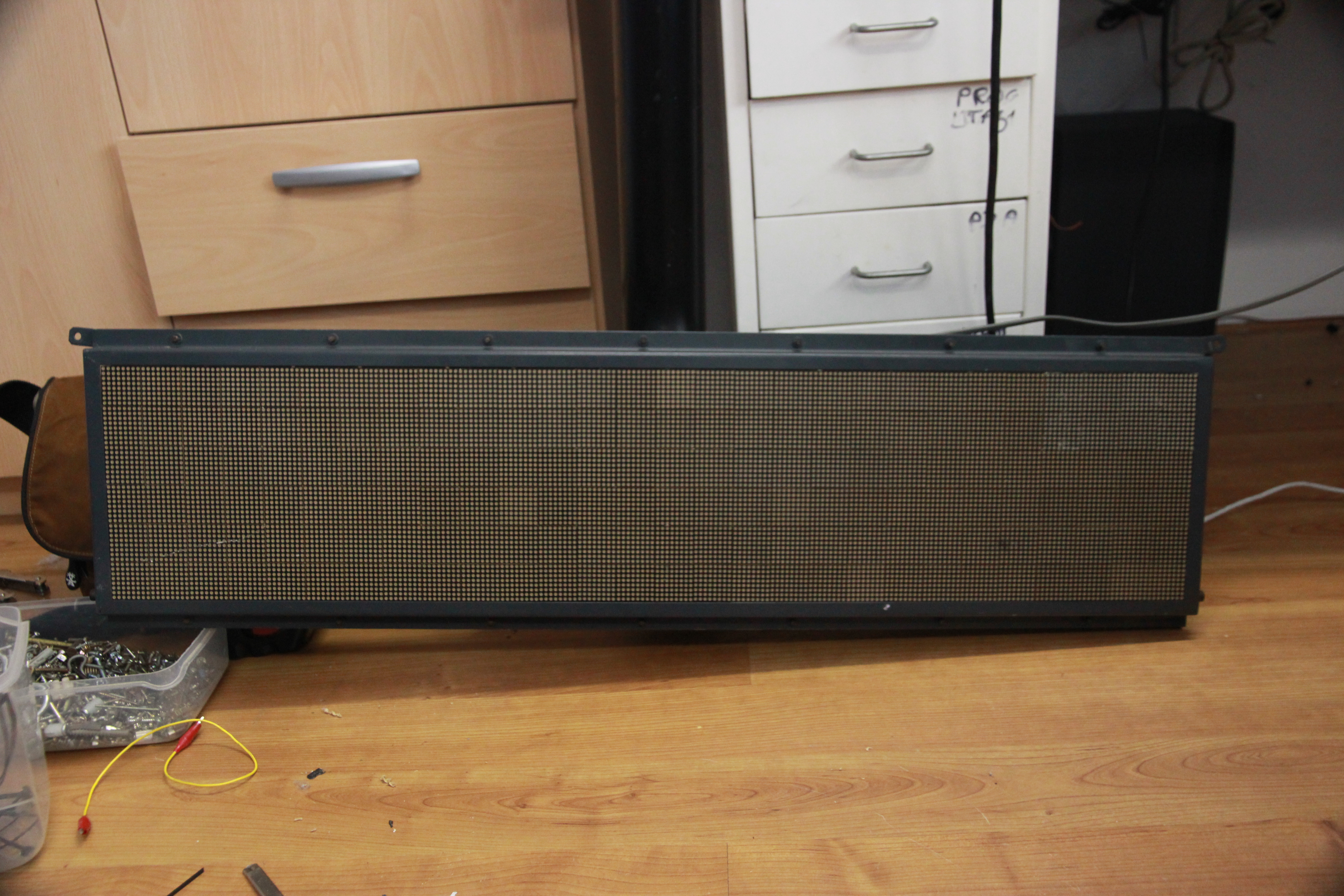
The LEDs themselves; all 10752 of them.
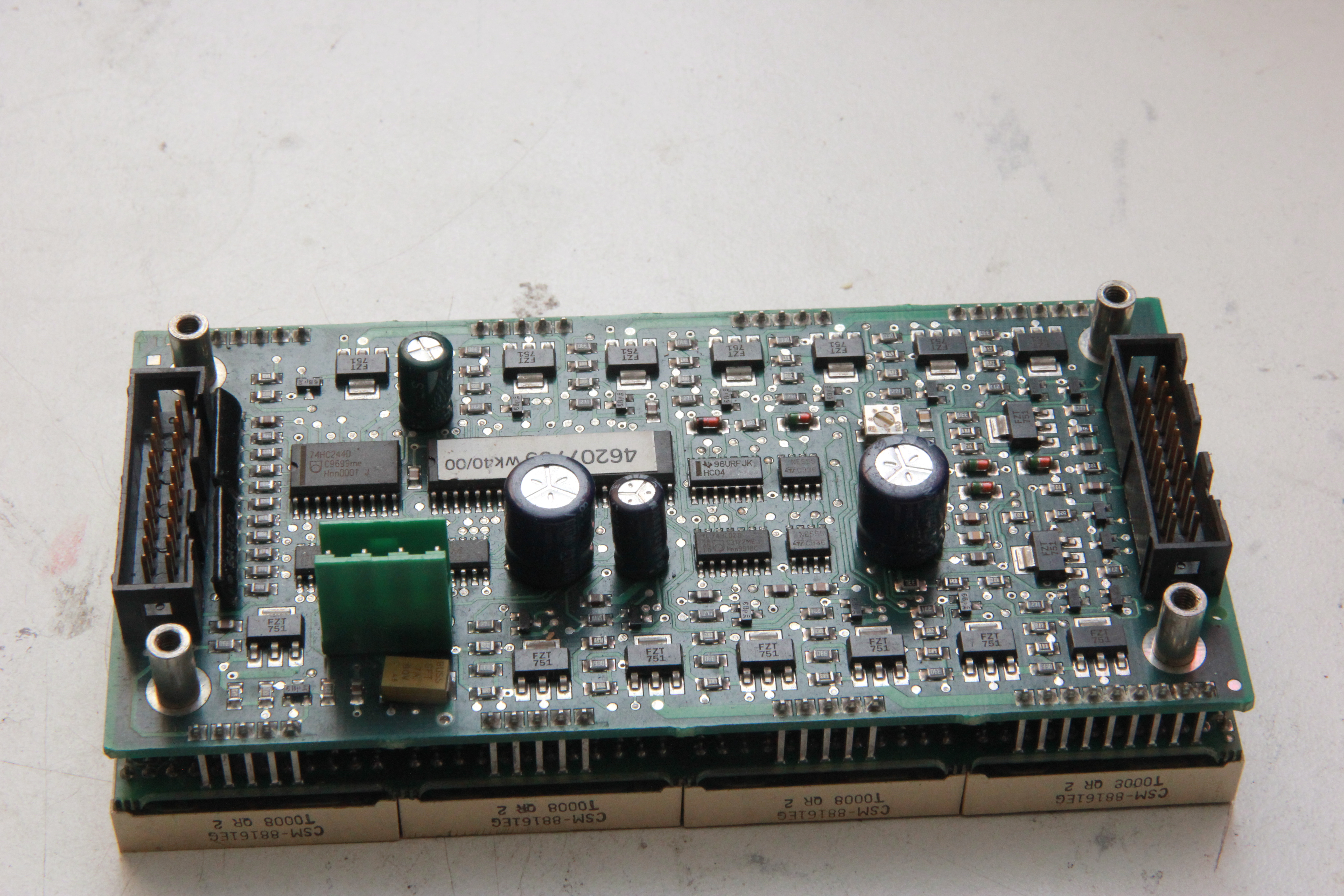
And one of the LED-modules. They consist of two PCBs: the top one has the buffer logic
and row driver transistors, the bottom one contains the series resistors and the column
driver ICs. The modules have 32x16 LEDs each, and 7 of them are daisy-chained to
form one 224x16 row. Three of these rows make the full 224x48 LED-board.
1 Next »