Hardware design
Ofcourse, the basic prototype should be enough to act as a basic clock radio, but I also wanted some extras I couldn't immediately prototype. I also wanted some hardware safeties, so even when the Carambola would decide to kernel panic, the machine would still be able to wake me up. That's why the final schematic differs a fair amount from my quick prototype. Here's what I ended up putting on the final PCB. If you want to know the exact value of the parts, please refer to the Bill of Materials.
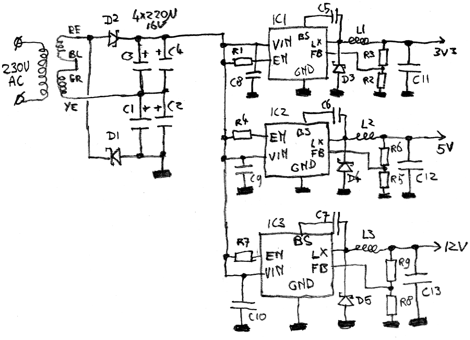
First of all, there's the PSU. It's not much different then the prototype: D1 and D2 plus C1-C4 convert
the 10VAC into 28VDC. From there, there are three buck-converters that use that voltage to generate the
12V, 5V and 3.3V for the rest of the hardware. The buck-converters are built around AOZ1282CI chips;
they are switchers that can work at almost half a MHz, keeping the rest of the components
small. They are rated for 1.2A, which is more than enough for the hardware they power here.
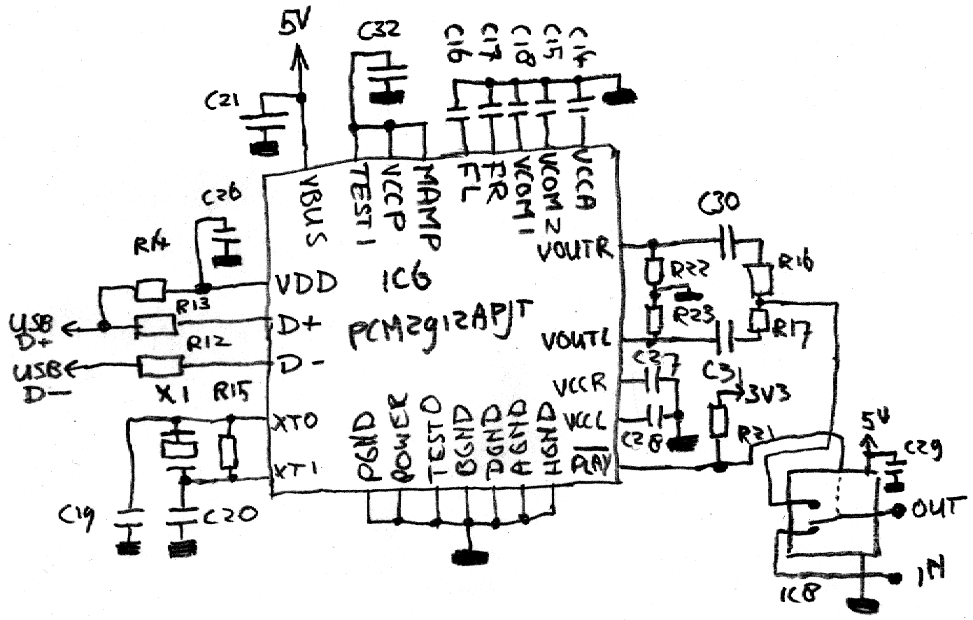
To be able to stream Shoutcast webradio, I added an USB sound IC to the mix. The chip I ended up
picking was the Texas Instruments PCM2912, an USB stereo DAC
in a TQFP32 package. One of the nice things about this chip is that it has a /PLAY-output which goes low
as soon as the chip actually is outputting a stream. I use that here to drive an analog switch in the
form of IC8, which is a tiny SN74LVC1G3157 analog switch. This switch disconnects the FM radio from
the amplifier and splices in the USB sound chips output. The advantage here is
that it gives some security for if the sound playing process on the carambola encounters problems
and is killed: the clock radio will automatically switch back to good old FM reception and still
wake me up.
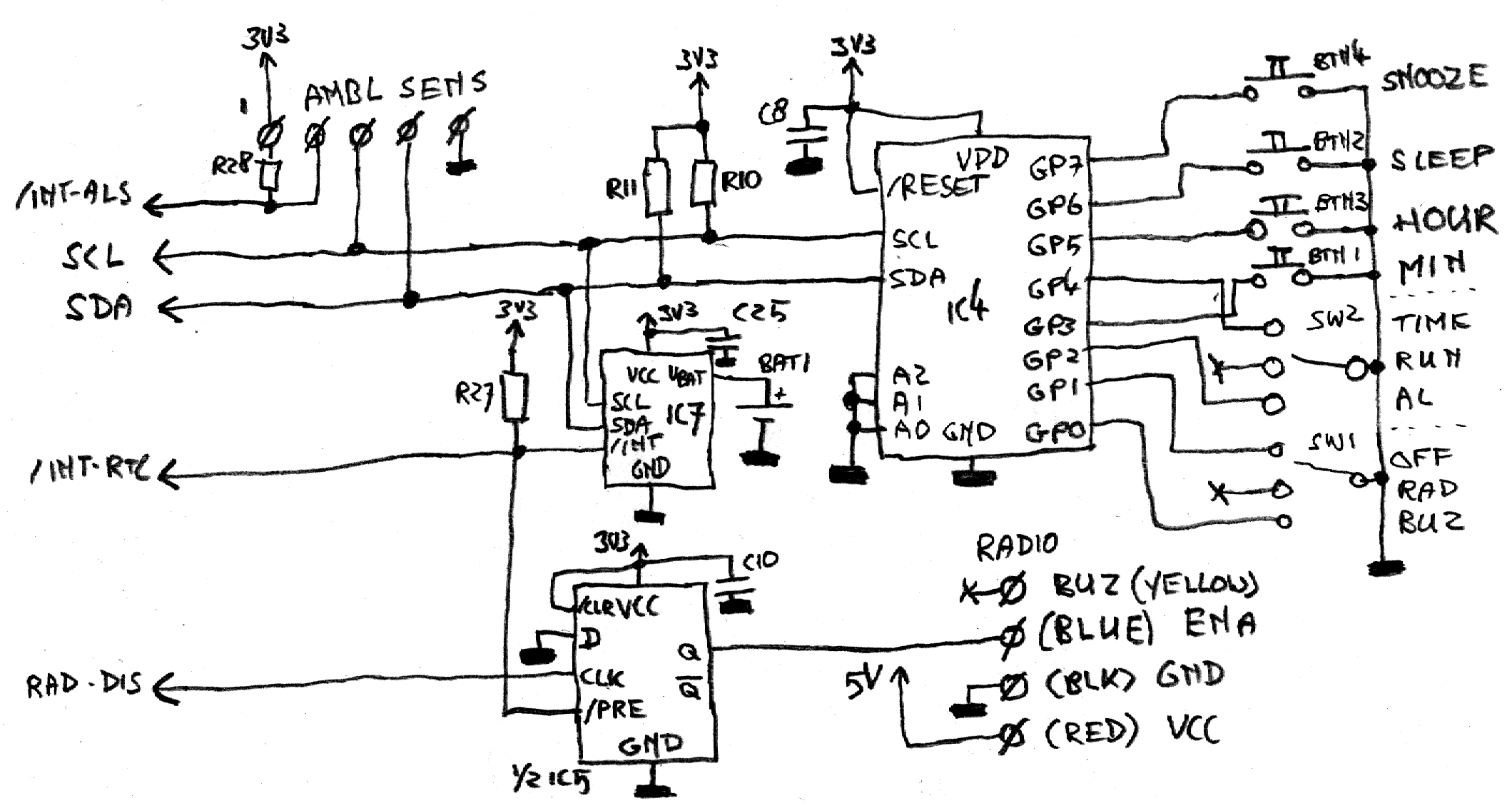
A lot of peripherials are connected to the I2C bus. On the rightmost side is IC4, which is an MCP23008
I2C I/O-expander. This basically gives the Carambola eight more inputs, and I have connected all the
buttons and switches the clock radio has to this chip. To the left of this is IC7, which is a DS3231
RTC chip. There's a reason this is a different chip than the prototype has: this RTC has an alarm
function and an associated interrupt output. Apart from leading this
line back to the Carambola, I've also tied it to the /PREset input of IC5, which is a dual D-flipflop:
if the alarm goes active, the flipflop output will go high and the radio will switch on.
By doing it this way, the alarm will always turn on the radio, even if the firmware on the Carambola
is out to lunch. The Carambola can turn the alarm off again by actively generating a high-low edge on a
GPIO.
A third component connecting to the I2C-bus is the ambient light sensor. I chose an Avago APDS-9900 for this, which is a combined ambient light and proximity sensor. The plan was to use the proximity sensor as an alternate snooze button, but I never got that to work behind the red plastic front of the clock radio.
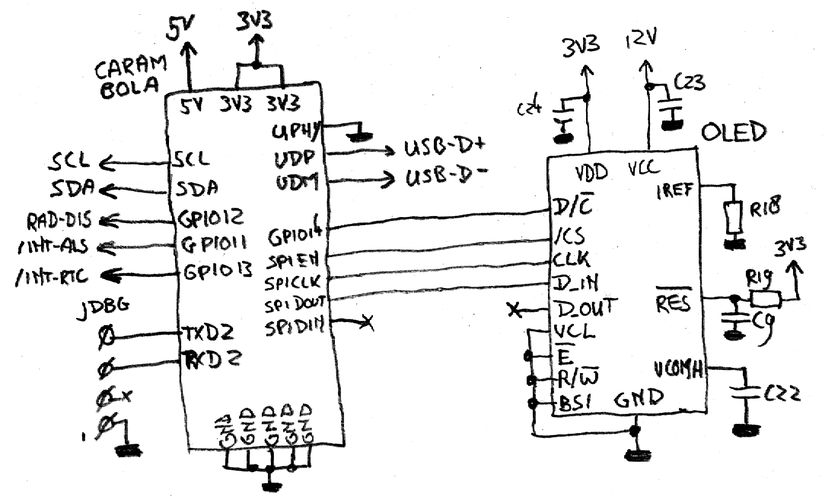
Finally, the Carambola and the OLED-display itself. No surprises here: the Carambola is interconnected
to the OLED using the SPI-port. The OLED needs a resistor (R18) to set the current as well as a small
reset circuit, made using R19/C9.
So, now all the components are know, it's time to replace the interior of the clock radio.