Hardware
For the Internet speed measuring part, I decided on using the simplest ESP8266 module, the ESP-01. I still had some of them in store, they have WiFi connectivity and even with only 8 pins, it should still have enough connectivity to pull this off.
Unfortunately, the ESP8266 by itself isn't enough to make this work. A dekatron works, in short, by transferring the ionization of neon atoms. At the moment you apply voltage to the dekatron, it will light a random one of its electrodes. By applying two pulses to the guide inputs, you can make the glow jump to the next or the previous electrode, dependent on the order of pulses you apply. Making the neon gas inside the dekatron glow, however, requires a voltage of 300-400V, and that voltage also needs to be switched to ground on the guide electrodes.
The usual way to generate 400V for a dekatron is to use the 230V that comes
out of a wall socket and put it into a voltage doubler. I'm not a big fan of
gadgets like this running directly off the mains voltage, so I decided to
go a different route. Some Googling turned up a schematic someone used
to control a dekatron from an AVR,
and part of his approach was to use a boost-converter combined with a multi-stage
voltage doubler to get to the required voltage. The boost-converter is controlled
by the AVR running the show. I liked this setup, and decided to 'borrow' the
idea for my own device. That being said, this is the schematic I came up with:
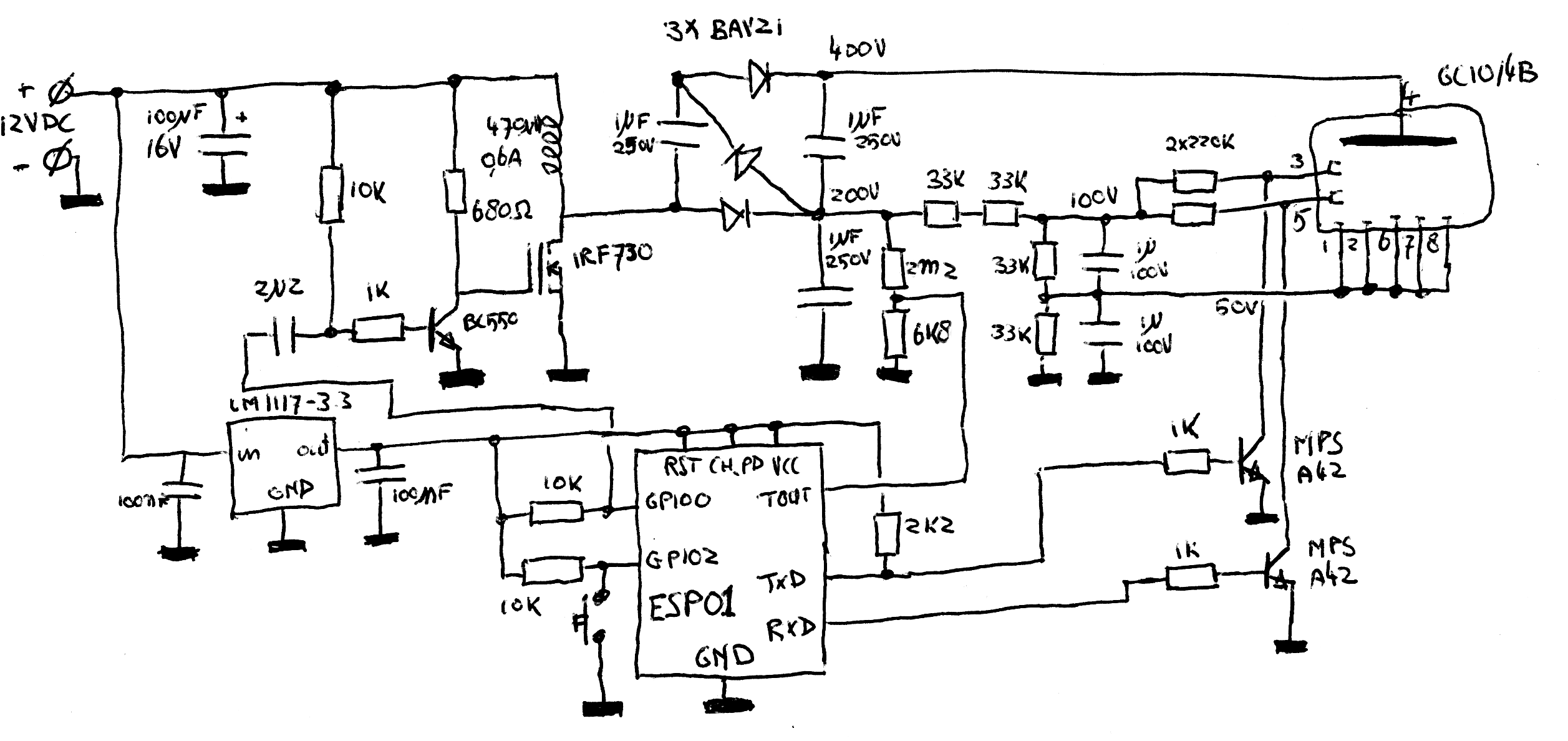
In the top left, the IRF730 and the 470uH inductor combined with the first diode of the voltage quadrupler form a basic boost converter: if the mosfet conducts, it will pull a current through the inductor. If it does not conduct the current will keep on flowing but has nowhere to go other than through the capacitors in the voltage quadrupler, which then will get charged. The IRF730 has a gate threshold voltage of 5V if you want it to conduct at least 1A, which is less than the 3.3V the ESP8266 runs at. To remedy that, there's a BC550 transistor which works as a level converter.
After the voltage quadrupler, there are a few resistive dividers to generate the other needed voltages. The 2.2M/6.8K divider will divide the 200V into a voltage of about 0.6V that varies linearily with the output of the voltage quadrupler. The ESP8266 measures this voltage through its internal ADC and adjusts the boost converters duty cycle accordingly. The ESP8266 also can control 2 MPS-A42 high-voltage transistors to switch the guiding grids; these signals are what actually makes the dekatron spin. These signals are connected to the TxD and RxD pins of the ESP01 module: the firmware disables the UART that's normally on these pins so they can be used as normal GPIOs.
The rest of the circuit around the ESP01 module is pretty simple: there's a simple 3.3V power supply built around an LM1117-3.3 to power the module and some pullups to make the module power up in the right mode. The pushbutton connected to GPIO0 is read out in software: if it is pushed for more than 3 seconds, the module will go into softap-mode. You can then connect to it over WiFi in order to choose an access point it should associate with.