The design
So, on the last day I had to myself before April the 1st, I set to work. What did I need? First of all, something that could play samples would be useful. I knew that the guy running Elm-chan.org had some code to make an ATTiny85 play wave files from an SD-card. If I used that, I'd have the advantage that my collegues could put new sounds in the doorbell themselves.
I started with this:
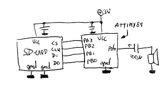
The schematic doesn't look like much yet but accomplishes a lot: the ATTiny85 interprets
the FAT16/32 filesystem on the SD-card and plays out the .wav-files on it, using
a 250KHz PWM signal. That is then routed to the speaker. You'd expect such a simple
setup to sound like crap, but the quality of the sound is actally quite good! This
is mostly because the ATTiny85 has a fast PWM module which can output PWM signals at
a quarter of a MHz. There's
just one problem: it's not loud enough. The PWM-signal the ATTiny85 sends out has an
range of only 3V, and only when the speaker isn't overloading the lone output pin.
There are two ways of amplifying the signal. The first is simply throwing an
analog amplifier into the mix. I didn't have such an IC in my spare parts bin, so I
had to find another way. Remembering the PWM-signal still is all-digital and only
gets analog in the speaker, I picked an unconventional part to do the job of
amplifying it: an L293. This IC houses 4 H-bridges and actually is meant for motor
control. It would suck as a conventional amplifier, but it can switch its output
from ground to Vcc and back in 300ns max. That means it won't be able to completely keep
up with the output of the AVR, which can output pulses as short as 15nS,
but it's good enough for a doorbell. I integrated it into my schematic
like this:
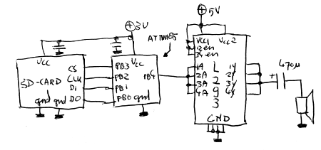
So, with the L293 installed, the schematic sent a nice and strong 5Vpp signal to the speaker. While this was much stronger than the original signal was, it still didn't suffice as a doorbell: the (8-ohm) speaker could only be driven with a maximum power of about three quarters of a Watt. Aside from this, the schematic now needed two power supplies: one of 2.7 to 3V for the microcontroller and SD-card and another of 4.5V or higher to power the L293. The idea was to run the circuit on 2 LiIon batteries, totaling at 7.2V. Some power supply handling was in order.
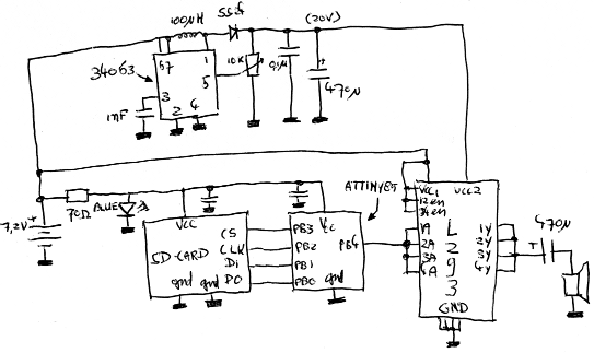
Two things have been added here. At the top, there's a 34063, which is a boost-converter
IC. This is used to convert the 7.2V the LiIon batteries emit to a nice 20V to feed
into the L293. The other power supply is a bit more difficult to see: it's the 70 ohm
resistor plus the blue LED next to the accu. The blue LED has a forward voltage of about
2.7, and the resistor is used to not send too much current through it. The LED-stabilized
2.7V is then used as a power source for the SD-card and the ATTiny85.
The addition of the step-up converter immediately made the circuit more doorbell-worthy: instead of the lousy 3/4th Watt, the poor little speaker now got to make its noise powered by almost 13W worth of power.
There was just one more addition needed: the doorbell-switch itself. With the current schematic, the AVR played a random wave-file on power-on and then stopped. I could have wired the doorbell button in such a way that the AVR would play the next sample when it detected a button press, but that meant both the boost-converter and the LED would be on all the time, drawing power from the batteries. In that case, I'd have to recharge them every day or so, which I wasn't planning on. I had to devise another way.
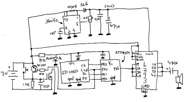
As you can see, there's a bit of discrete circuitry added to the schematic. Normally,
the N-channel mosfet disconnects the batteries negative pole from the ground, disabling
power to the doorbell. As soon as the button gets pressed, it'll charge the 22uF capacitor
which will then make the gate of the mosfet high and the doorbell will start to play
a sample. When it plays the sample, it'll keep sending a clock signal over the CLK-line
to the SD-card. Every time this happens, the BC550 will re-charge the capacitor which
means the circuit gets powered a little bit longer. When the sample is fully played,
though, the CLK-line will go high, the BC550 won't charge the capacitor anymore and
the capacitor will discharge over the 10K resistor, eventually switching off the
circuit. This does add the restriction that the wave files must have a fairly high
sample rate, or else the avr will temporarily stop clocking the SD-card, switching everything
off prematurely.