Hardware
For the hardware, the main sticking point is that it should be as power efficient as possible: a clock that you need to recharge every week is not a good clock. That informed the design by a fair bit.
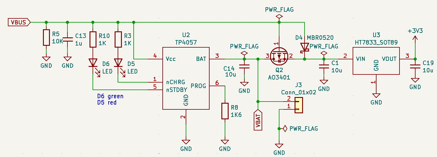
First, the power supply. Power is supplied by a classic Nokia BP-6MT LiIon cell. These are about 1100mA at 3.7V, which should be enough for ample runtime. The design has a classic TP4057 IC that allows recharging from an USB-C port (VBUS in the schematic above); that way I wouldn't have to disassemble the digits for charging. A HT7833 LDO converts the LiIon cell voltage to a stable 3.3V; it has a nice and low quiescent power use and can provide 500mA which normally (foreshadowing...) is enough to run the main chip.
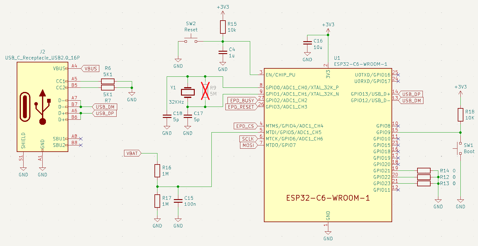
The aforementioned main chip is an ESP32C6, in the form of an ESP32-C6-Wroom-1 module. The ESP32C6 has an integrated low-power coprocessor, which I could use to change the Eink content with as little wasted energy as possible. It has a 32KHz crystal connected, which can be used in deep sleep mode to keep the time somewhat precisely. The module is programmable via the USB-C connector also used to charge the battery. There's a reset and boot button; normally you would be able to reset the ESP and put it in programming mode solely via the USB-serial-JTAG device inside, but in deep sleep that is nonfunctional so I needed physical buttons to be able to reprogram it. There's also positions for three zero-ohm resistors (of which two are used) to select the position of the digit in the clock: by populating or not populating them, you form a binary number that is then read by the firmware to display the proper digit.
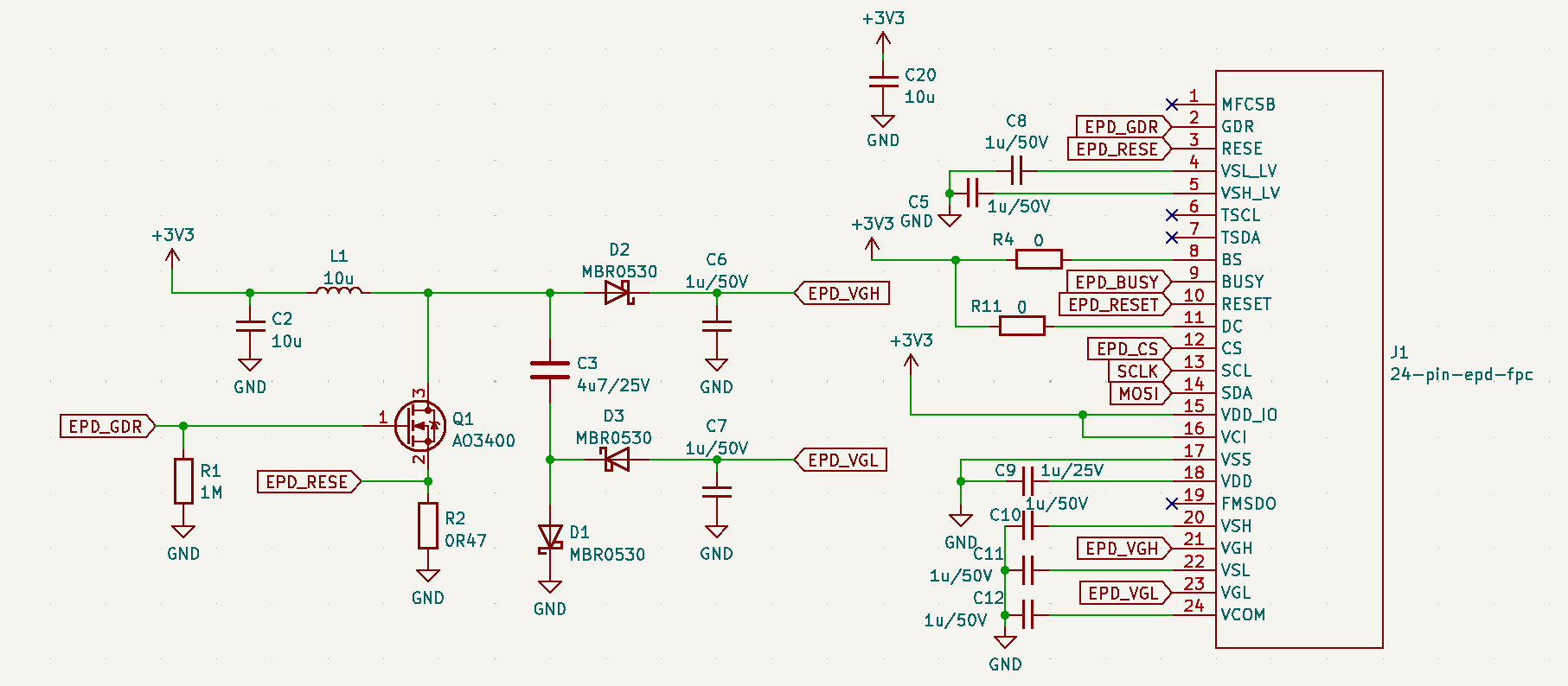
Finally, there's the Eink display itself: a Good-Display GDEY037T03 screen. This 3.7" black-and-white has a pretty high resolution of 240x416 pixels. It also supports multiple refresh modes, which is useful as it allows me to get rid of some of the annoying flickering that E-ink displays sometimes show when they refresh. The schematic above has the 24-pin FFC connector to connect it, as well as the components it needs to allow it to generate the voltages to change what's being displayed. This is all more-or-less according to the datasheet. Care has been taken to route the I/O pins to GPIOs that can be driven by the low-power coprocessor; not all GPIOs on the ESP32C6 are capable of that.
All this was put on a PCB with a size slightly smaller than the size of the Eink display, so it could 'hide' entirely behind it. The PCB also has a cutout for the battery.
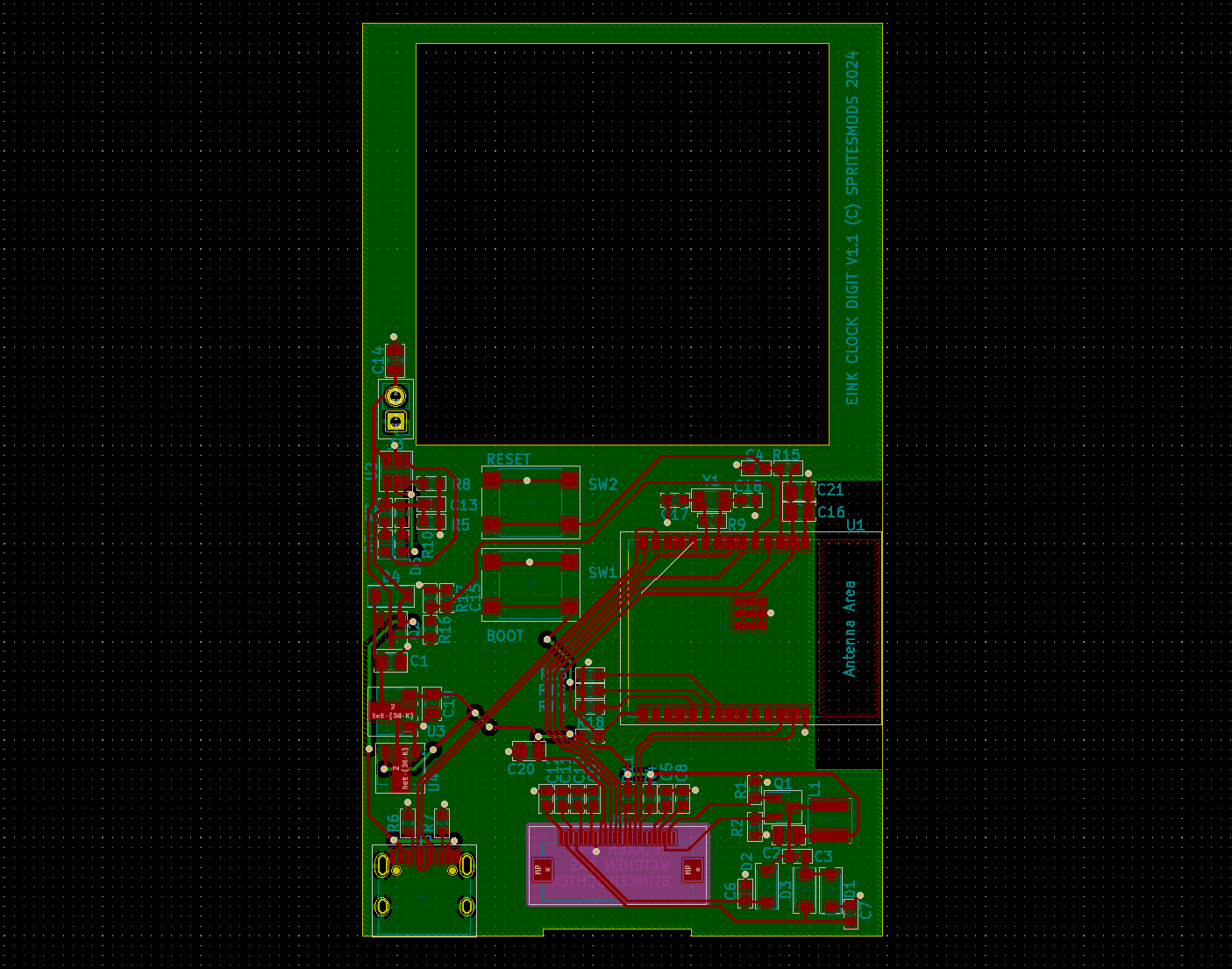
The entire thing was assembled with double sided sticky tape: the E-ink on the front, behind it the PCB, inside that the battery, Finally, a piece of hook-and-loop type tape is used to stick the battery to the wall: that way I can still easily remove it if I need to update the program or change the battery.
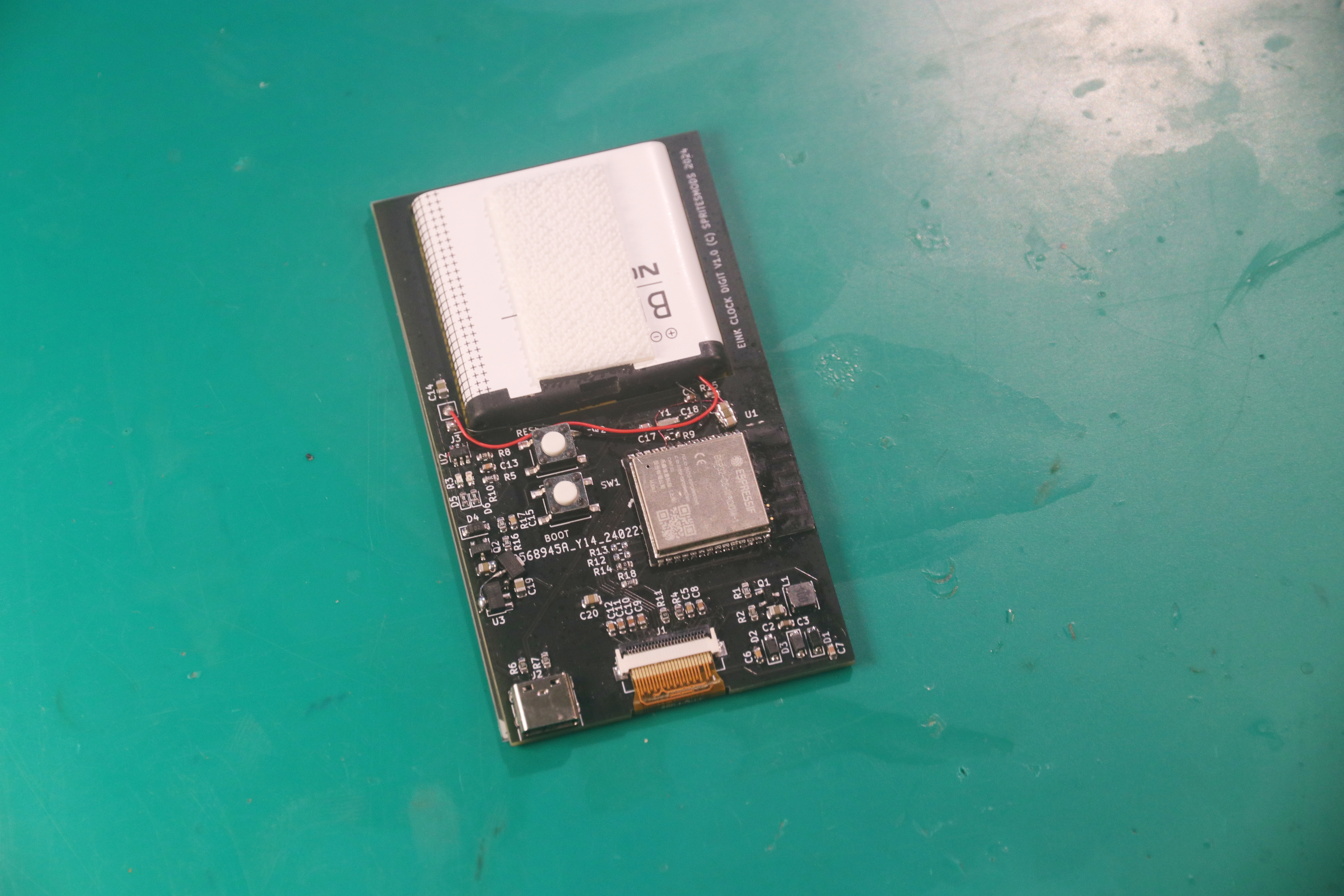
This sandwich-type setup has one downside, though: there only is a thin layer of PCB between the antenna and the back of the E-ink display. The back of the E-ink display is full of conductive electrodes in the form of the matrix that control the E-ink pixels. As far as 2.4GHz is concerned, it may as wel have been a solid copper ground plane; it does an excellent job of majorly detuning the antenna. Now, I kind-of accepted that this could happen beforehand: worst case I'd have sub-optimal WiFi range, but the access point is nearby and I wasn't concerned about transfer speed being impacted. What I did not foresee was that this would have a second effect: the de-tuned antenna makes the RF amplifier use a lot more power during calibration, even more than normal. This overloads the 500mA-capable LDO, which leads to a brownout, which resets the chip.
Obviously, I could have fixed this by redesigning the PCB, maybe having the antenna stick out or having more distance between it and the E-ink screen, but I decided on a simpler solution:
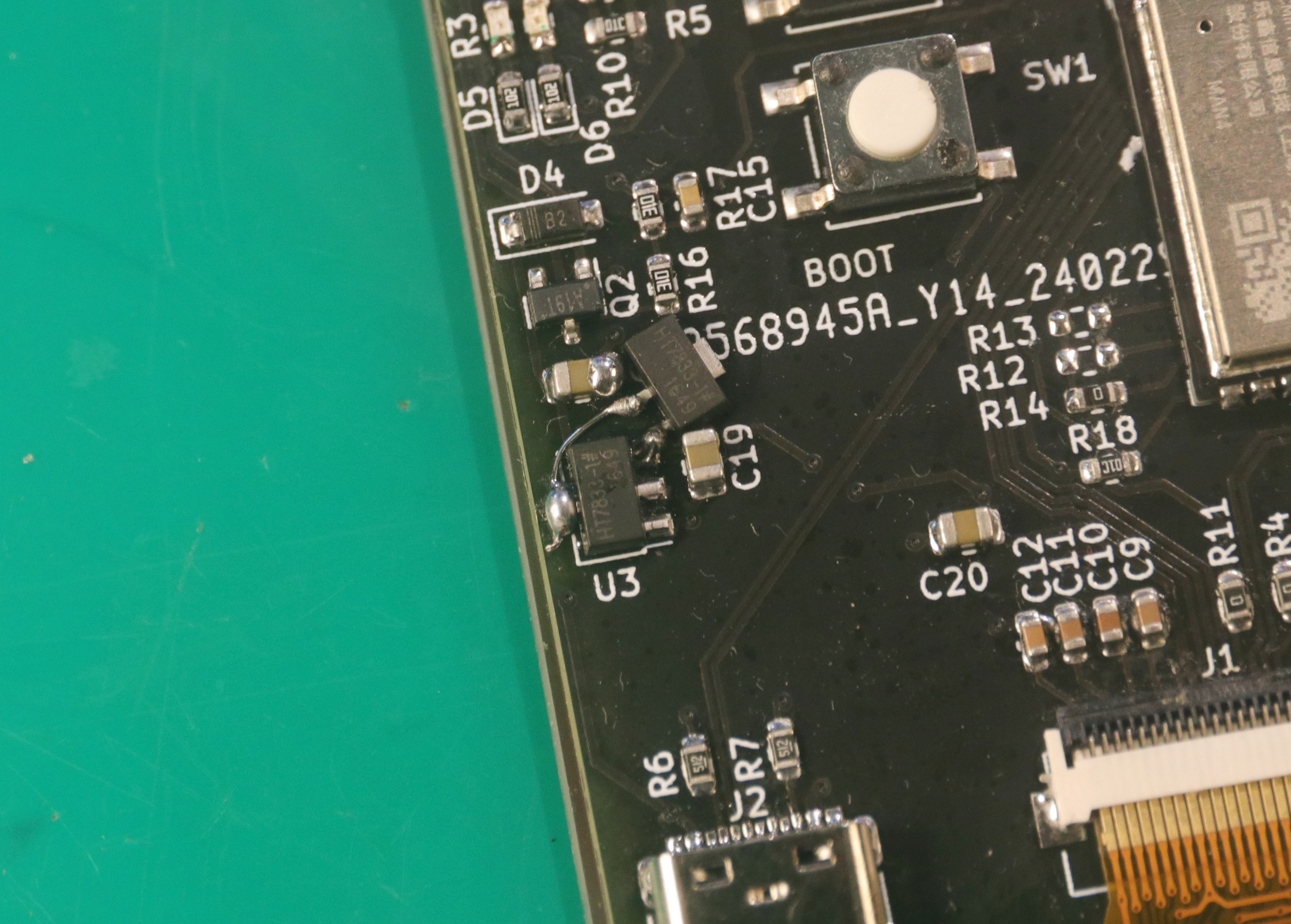
The two LDOs, combined with a slight reduction in Tx power in the WiFi settings, stopped the brownouts from happening. It's not the best solution, but given that WiFi is used for very little in this project, I deemed it acceptable.