First prototype
As described on essentialscrap.com, an e-ink display is a fairly weird beast, mainly because of how it works. Basically, the display logic itself consists of a shift register to select a row of pixels, plus a 'shift register' you can load with 8 bits at a time to clock in the pixel values for the selected row. This shift register has two bits per pixel, to select if a pixel should go black, go white or stay the same. By shifting display changes like that through all the rows, you can partially or fully replace the image that's on the screen.
Because the display works with electrophoresic ink particles, it needs a fairly high voltage to attract and repel them. In this case, +15V and -15V is needed. In the E-ink screen, these voltages are switched with two MOSFETs per pixel, and these need a gate voltage that's more than the positive and negative 15V: on this display, +22 and -20 volts are required. The display also needs a standard 3.3V power rail for its logic, and a display-specific Vcommon voltage of about -1 to -3 volts.
My normal approach here would be to make a prototype on e.g. veroboard and then try to see what I'd need
before moving on to something more permanent. In this case, that would be a bit difficult: for example
the header that connects the E-ink panel has 39 contacts spaced only half a millimeter apart. That
would be pretty fiddly to wire up wires too, so I decided to whack together a small PCB with all the
important parts: a DC-DC-converter to generate the required +22/-20V, some LDOs to create the
just as important +15/-15V, a 3.3V LDO for the supply voltage, an opamp and trimmer combo to
create the Vcommon the display needs and a microcontroller to control it all.
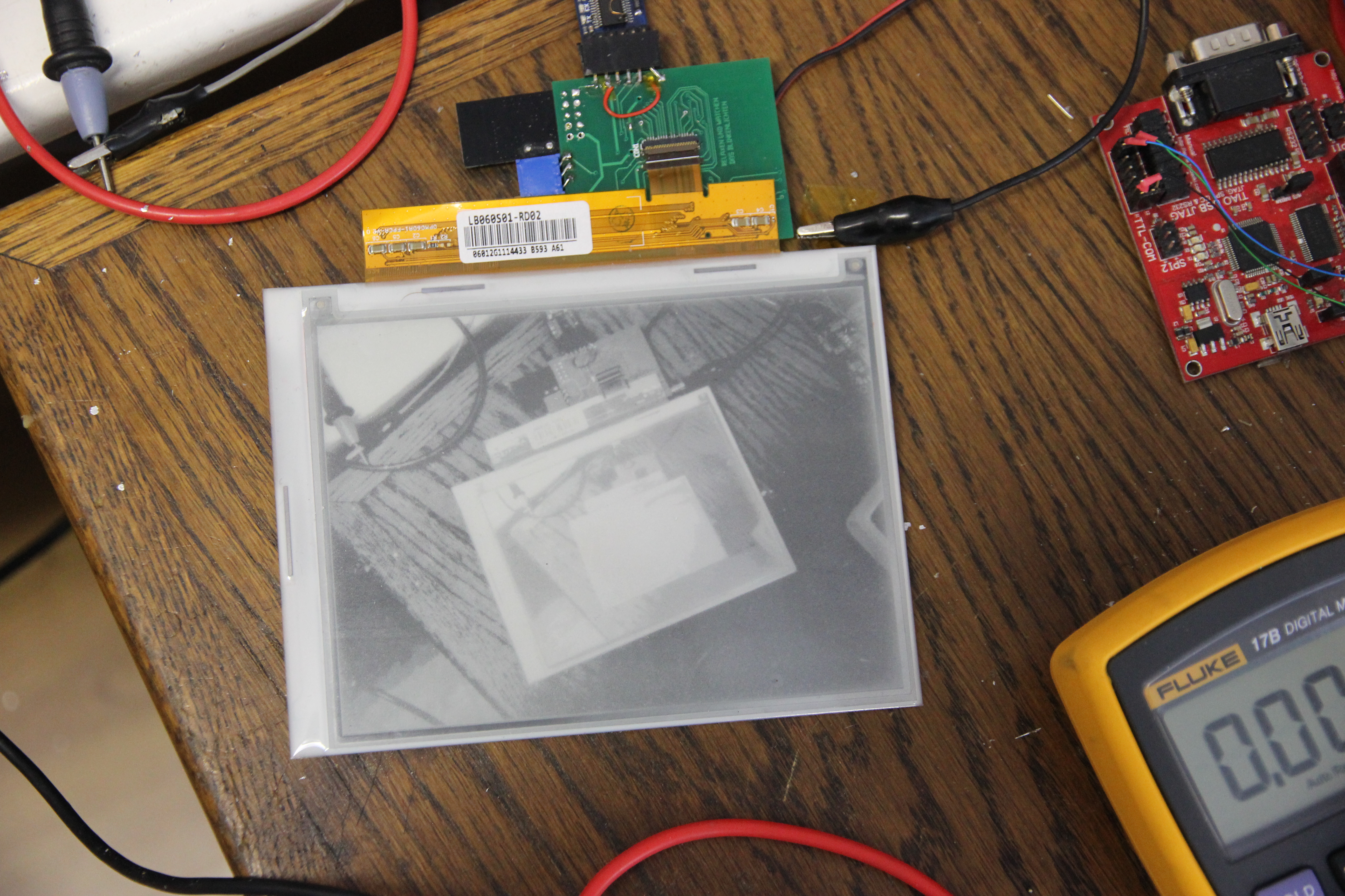
After I populated the PCB, I decided to implement the process described on the aforementioned Essential Scrap website. After some fiddling around, it actually worked and I could display an image!
The weird thing was: I only could get an image on one of my E-ink screens. While looking at why this could be, I noticed that it actually had a different part number: most of the displays I had had 'ED060SC4' as a part number, while the working one had 'LB060SC4' as a part number. According to the Internet, the parts should be 100% compatible, and when I tried to get more displays advertised as LB060SC4s, the seller actually sent me ED060SC4s claiming they're the same thing anyway.
While I now had a working E-ink display, I really wanted to have something people could reproduce, plus I didn't want to throw away the other displays. That meant I would have to get my ED060SC4 displays working too. I tried fiddling with the timing, hooking up the pins marked as 'unused' to various voltages and hooking up extra voltages I saw in the schematics of some E-ink readers, but the display didn't want to do anything more than display a single grey page. Disheartened, I decided to let the project be for the time being.