Teardown
To take the Frekvens apart, all you need is a Phillips screwdriver and perhaps a knife. You will also need a fair bit of persistance, as this thing does not come apart easily: the construction is somewhat complicated and some things are siliconed in place, possibly to stop rattling or to make manufacturing easier.

Tearing the Frekvens box apart starts at the back. The box has screwholes on all sides except for the front; these can be used with the bag of assorted screws and straps that came with the device to secure it to other Frekvens gadgets. However, the screwholes on the back are a bit deeper and have actual screws that hold the case closed behind them.
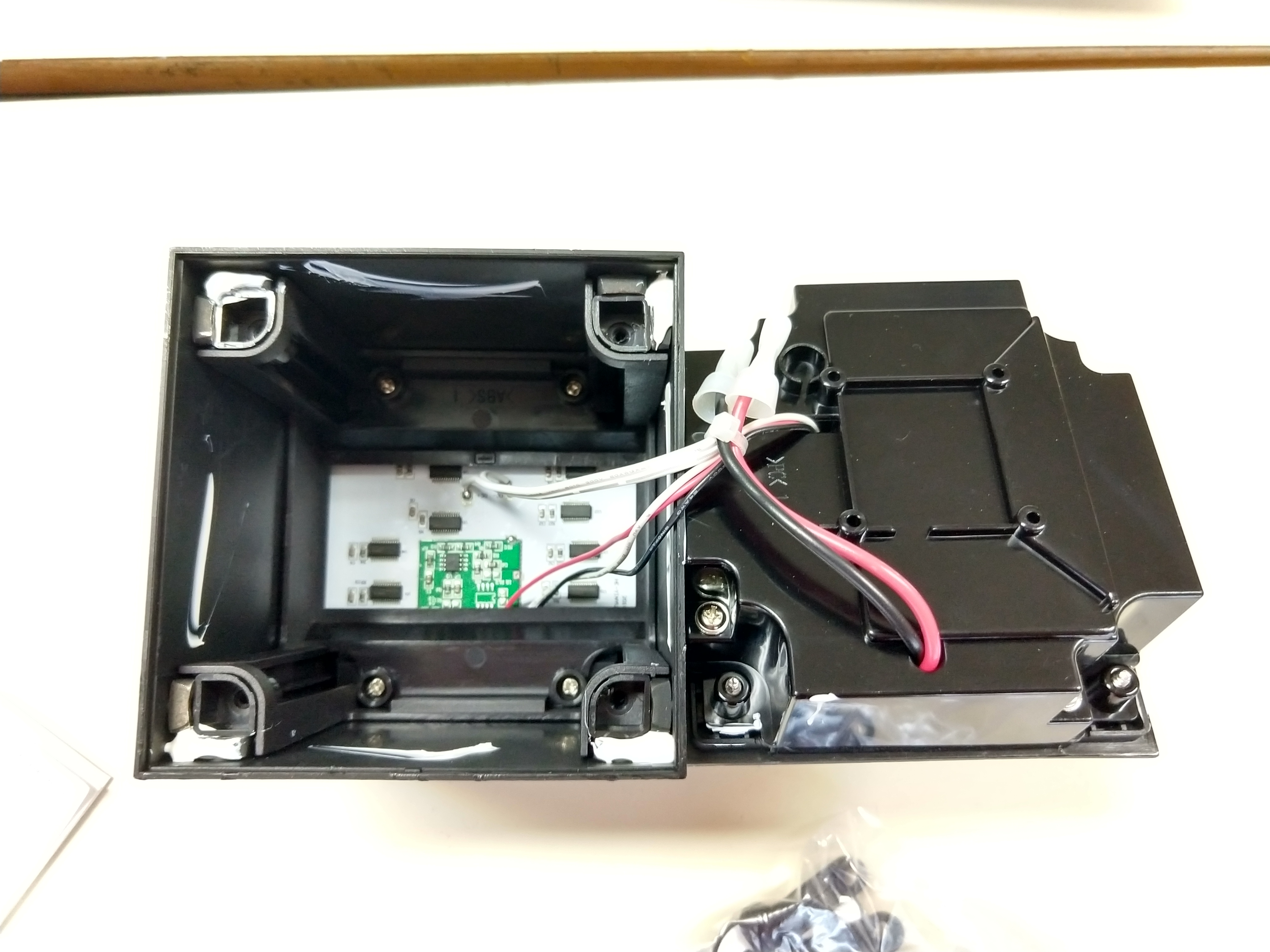
Taking the back off, we can see that all the screwholes actually contain metal inserts that have the threads you can screw into. Nice! That should give the screwholes a fair amount of longevity. It's possibly also a pain to manufacture or disassemble; the latter is complicated by the fact that we'll need to cut through the blobs of hardened silicone putty first.
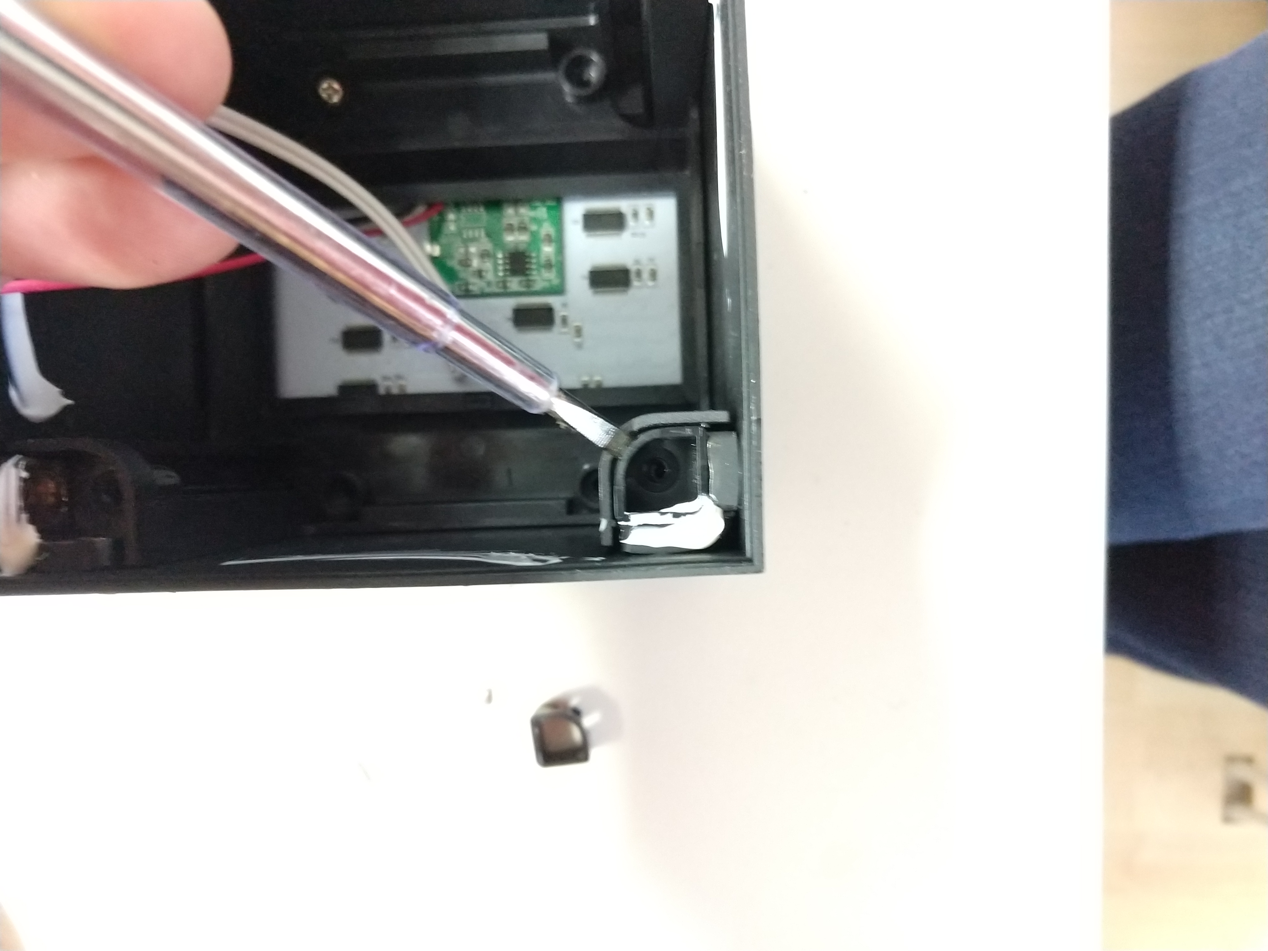
The inserts are actually kept in place by some more plastic inserts; these need to be removed first.
I don't have any more pictures of the rest of the disassembly, but after this step you can see four screws you need to remove, and then the process continues as before. Figure out what plastic bit holds the rest in place, cut any silicone putty, remove plastic bit. This continues until you finally can pull the main PCB out.
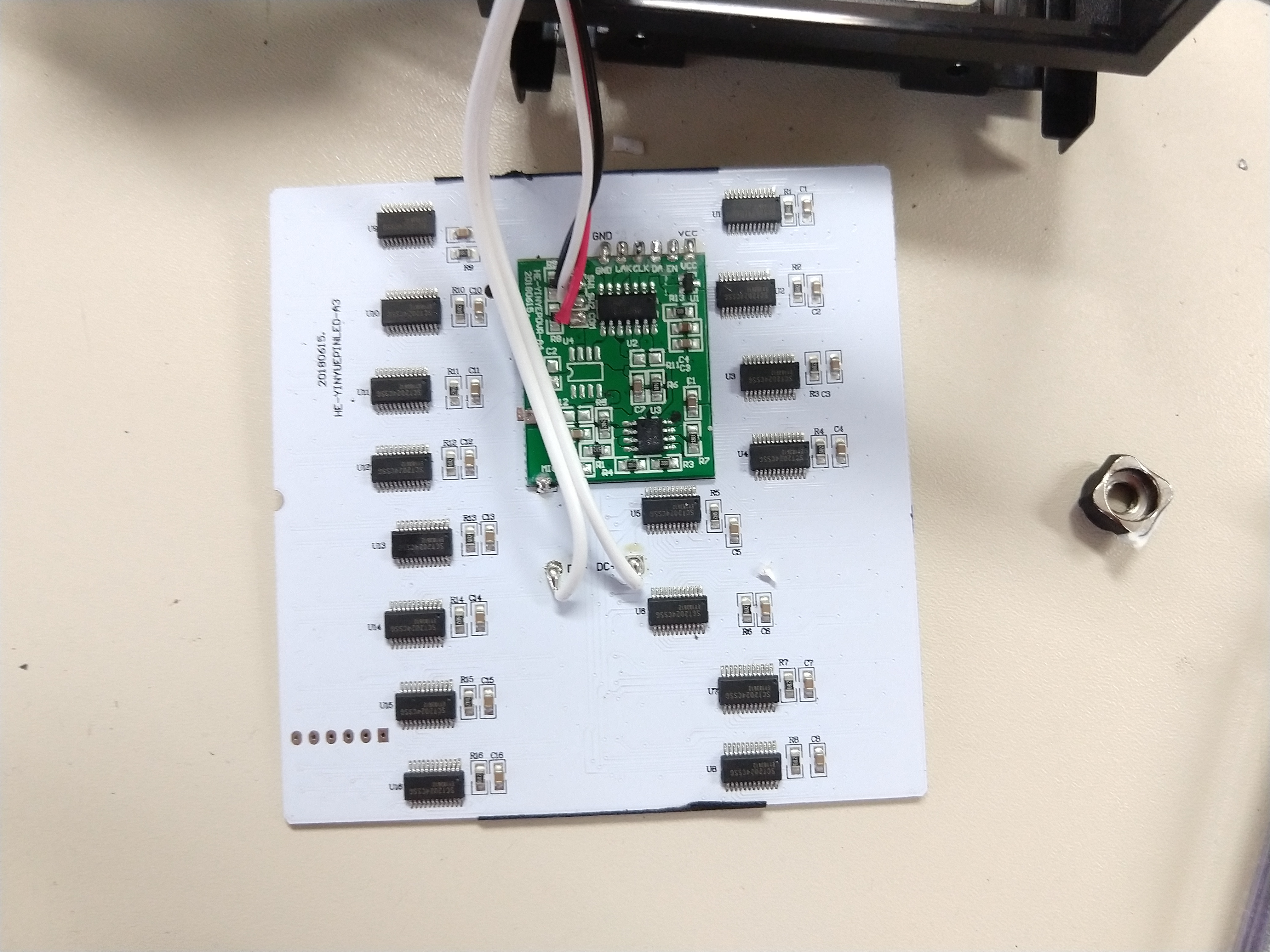
And here it is: the backside of the PCB. It turns out this actually is an assembly consisting of two PCBs: the white one is double-sided and carries all the LED drivers (and the other PCB) on the back while the front contains all the LEDs themselves. The design of the white PCB is pretty decent: instead of having the LEDs in a matrix, there are 16 SCT2024 constant current LED drivers. These LED drivers have 16 channels each so each LED is directly controlled. The LED drivers can only turn the LEDs fully on or off; there's no native grayscale support in the drivers itself. They're effectively shift registers with current-controlled outputs, and here they're all switched in series; the interface to the green PCB consists of the clock and data for that, a latch enable line, an output enable line and ground and power.
This green PCB contains whatever little brains the thing has: a microcontroller with a type number that gives no hits on Google and an opamp for the microphone. Interestingly, there are hints indicating the device was meant to be capable of more: there's a location for, presumably, a 24Cxx I2C EEPROM and a hint that the original design had an IR-receiver on the front. Perhaps the box was supposed to come with a remote control allowing you to create your own patterns? That may explain why the included ones look so lackluster.
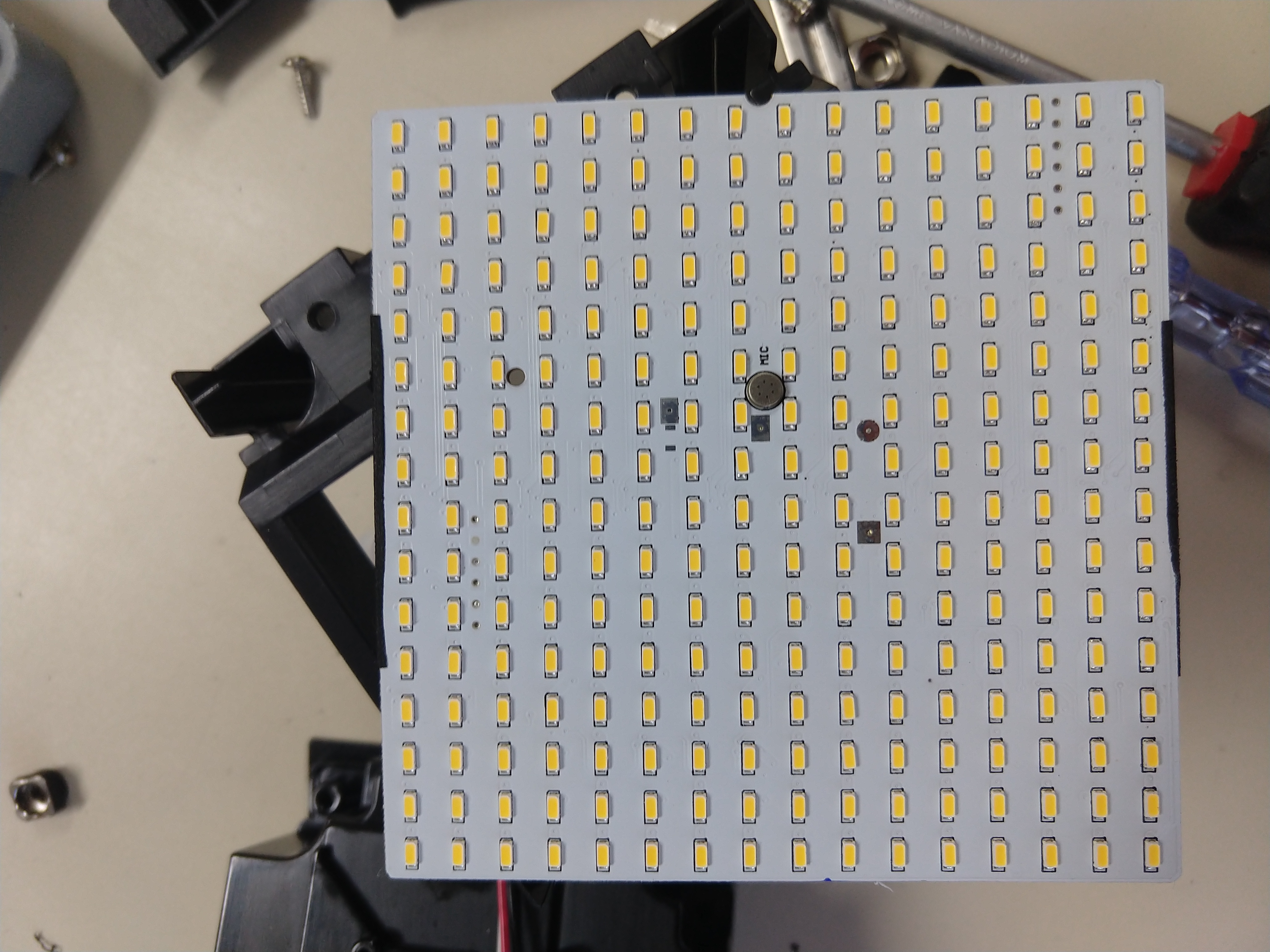
The front of the white PCB contains all the individual LEDs. There is also a tiny flat microphone soldered to this. I initially thought it was soldered onto the green PCB and just sticking out through a hole in the white PCB, but no, it's actually just really flat.
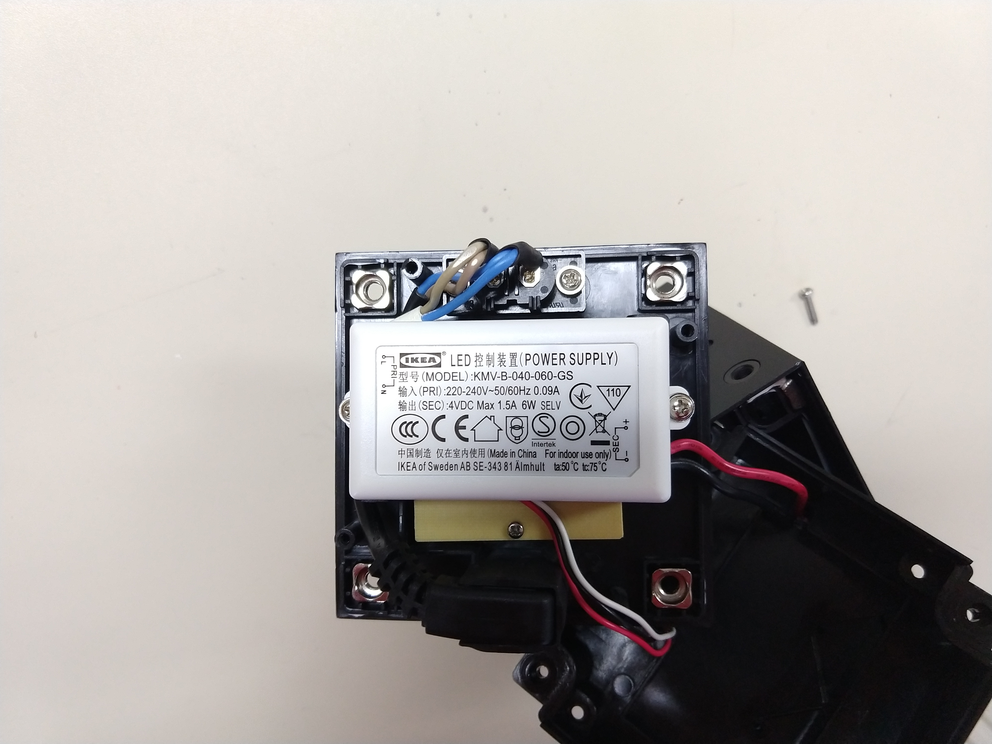
The remaining electronics are on the back. Nothing much: it's an Ikea-brand power supply outputting 4V. Under the power supply is a little PCB containing the two tactile switches for the buttons on the back of the box.
So, if we want to 'optimize' the design, there's a clear weak point: the little green processor board is better off being replaced by something more powerful.