Intro, theory
Most old PDAs use CCFLs as backlights. While such a PDA itself can still be quite useful, the backlight sometimes is old or damaged. You can, however, replace it with a more modern and power-friendly solution: white leds. To do that in a power-efficient way, a bit more is needed, though.
Intro
A few months ago, I bought myself a second-hand HP Jornada 680. Nice beastie: color screen, keyboard, rugged clamshell design, PCMCIA-slot, 133MHz SuperH-processor, can run Linux. Great for IRC, IM and mail: just insert an Orinoco wlan-card, boot Linux from a 512MB CF-card and you have an excellent wireless mini-terminal.
So far, so good, but even as I was looking at the PDA before buying it, the thing that struck my eye is that the backlight was kinda pink-ish. When I opened the display panel of the PDA, it turned out that the backlight was a tiny CCFL with attached inverter, and that CCFL was getting old. What do CCFLs when they get old? Exactly, emit a pinkish glow instead of the normal cool white light. Aside from that, they tend to get less efficient too, IIRC.
CCFLs for screens like this aren't used anymore: every manufacturer of small LCDs equips their screen with white LEDs nowadays. White leds aren't really rare either: SMD high-brightness ones already go for less than a buck apiece. I decided to let the Jornada join the 21st century backlight-wise: I ripped out the CCFL plus inverter and thought of a way to make leds go there.
Theory
(If you want to skip to the more practical stuff, just scroll down.)
Physically, getting the white LEDs inside the screen isn't that hard: the LEDs I ordered
were SMD, the kind that go into backlights of phones, too. They're small
enough to be soldered on a really small and thin piece of PCB and still fit in
the space the CCFL took earlier: with a nice spacing, I could fit 14 LEDs inthere
easily. The problem would be the control: the PDA
gave me 7.4V, directly from the 2 LiIon-cells.
White leds need at least 2.8V to make 'em light up and they give the maximum amount
of light with a current of 20mA. If I used a resistor in series
with every 2 LEDs, I'd waste almost 1/3 of my power on heat in the resistors alone.
The backlight wouldn't be efficient that way.
The most efficient way of placing the leds would be to have them all in series, with a single resistor to limit the current, or all in series with a constant current source of 20mA to drive them all. Both approaches had a problem: I needed to generate at least 40V before I could get the chain of leds to emit any light. There are ways to generate that voltage: a deviced called a 'boost-converter' could do it.

Figure 1
A typical boost-converter is shown in fig. 1: the (square-wave) output of the PWM-generator switches S1 on or off. If S1 is closed, the current I1 will run and a magnetic field will develop in L1. As soon as the switch is opened, the magnetic field in L1 will collapse, generating a current. The only way that current (I2) can run is by going through D1 and C1. Because a current runs through C1, it'll become charged a bit more and Vout will be a bit higher.
The value of I2 can be modified by adjusting the on-time of S1: if S1 is closed longer, I2 will be higher and C1 gets charged faster. If a load is attached to Vout, we need to match the current through that load with I2 if we want to keep the voltage in C1 at the same level. Tha's where the comparator and Vneeded are for: if Vout gets too low, the comparator will make the PWM-generator close the switch a bit longer and Vout wil eventually be the Vout we need again.
The boost-converter as lined out is a constant-voltage-source. What we need here is a constant-current-source: we want the current through the leds to always be 15-20mA. The change needed isn't that much: instead of comparing the output voltage to a certain value, we need a shunt (a resistor with a low value) in series with the load. The voltage over that resistor will be an indication for the current through the load: if we compare this current with a constant value and feed the result to the PWM-generator, we have what we want.
Practice
I was working with a few restrictions: First of all the components of the current source had to fit inside the space where previously the CCFL inverter was, and secondly the circuit had to be built with the components I already had: I had a sunday afternoon and evening for it and I was planning to finish it in that amount of time. So: no waiting for special components.
After some thought, I designed the schematic of the backlight controller. (fig. 2) It uses components I already had (ATTiny, resistor, capacitors) or could scavenge from old PCBs (78l05, mosfet, diode, inductor). The ATTiny has an A/D-converter with a built-in reference as well as a PWM-generator, so I decided that part could act as the controlling and PWM-generating logic. The Jornada has, besides the 7.4V and ground, an extra output which seemed to dim the backlight as soon as it went high, so I connected it to the Tiny13 too. The complete design should be quite power-friendly, with most boost-converters reaching 80-90% efficiency and the measurement resistor R1 using just a fraction of the power a normal LED series resistor uses.
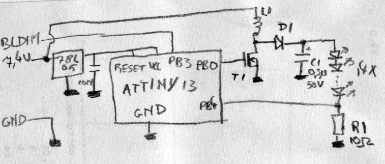
Figure 2
As you can see, T1, L1 and D1 don't have any type numbers or anything next to them. That's because I couldn't find it: I ripped them off old PCBs. T1 should be an N-channel mosfet capable of switching about 1A and D1 should be able to switch the same amount of current and withstand 50V when it doesn't conduct. You'll have to experiment with the inductor: coils ripped from laptop PCBs or laptop power supplies usually work OK.
1 Next »