Method
So, why is the video-interface so good for timing-critical things like this? Mostly because the video
generators of most SoCs still are compatible with the signals needed to drive old CRTs. CRTs work
by sending an electron beam over the screen, drawing whatever color you send to it at the place where
the beam happens to be. Timing is very critical: you can't really micro-manage the position of the beam,
so you need to send out the correct pixel value at exactly the right time to get a stable image. The beam
would go from left to right to draw a line of pixels, and at the end of the line move down a bit to draw
the next line, again from left to right, and so on. Every time the beam hits the bottom of the screen,
it will take a few lines of time to quickly move to the top again:

The timing of these things is taken
care of by the hsync and vsync signals: hsync signals when the electron beam needs to go back for a new
line, vsync means a complete image is finished and the beam needs to go back tot the top. Because
you don't want any pixels drawn while the electron beam is going back, a certain period before and after
the blank, no video is sent. These periods are known as the front- and backporch. For a CRT, the pixels
that are to be displayed are usually transmitted in an analog fashion. For example, for a color
depth of 16 bit, the video memory will contain 16 bit of RGB data for each pixel: 5 bits for the amount
of red, 6 for green and 5 for the amount of blue in a pixel. These pixels need to be sent out in a very
constant rate (the dot clock rate) because the electron beam can't be affected directly: the only way to get a static
image is to send out every pixel at exactly the same moment for every frame.
Modern SoCs don't have a direct analog output for CRTs anymore, but directly output the 16 bits of color info on a bus. The simplest way of outputting that digital signal is having a parallel bus: 16 electric wires containing the direct binary values of the pixels. You can either send this 16-bit value to three D/A-converters to get your analog signal back, or connect a TFT with a compatible parallel bus to it directly. The iMX233 SoC on the Olinuxino has such a 16-bit bus as an output option.
Even while this signal now is digital, the timing still resembles the old CRT driving waveform very much: the image is sent out from left to right, top to bottom, with no pixels transmitted at the back- and frontporches: while they can do without. With TFTs, the porches basically are superfluous, but almost any TFT will still accept them.
So, how does this information correlate to driving WS2811 ICs? Well, if you somehow manage to
disable the syncs and porches, the LCD controller of the iMX233 basically gives us a way to output a
pre-defined 16-bit signal on the 16 lines of the LCD-bus, with each 16-bit word lasting a well-defined
period of time. Ideally, you can define a framebuffer with a lot of 16-bit words in it, and the video
hardware will make sure the bits in the
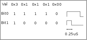
16 bit words are output on the 16 datalines of the LCD-bus. This allows us to pre-define signals. For
example, say I'd write the pixel values 0x3, 0x1, 0x1, 0x1, 0x0 into the framebuffer and configure
the video hardware to spit out these values with a dot clock of 4MHz. This means a new pixel value
would be sent every 0.25uS and with the pixel values defined, that'd mean I would have generated the
WS2811 '1' waveform on the 1st LCD dataline and the WS2811 '0' waveform on the second:

This basically means we can use the video hardware to do all the hard work of timing the signals to arrive at exactly the right moment. All we need to do is write the correct waveform for the WS2811 bits into the video memory at our leisure, and the hardware will take care of the rest. Sounds like a doozy, doesn't it?