Data encoding
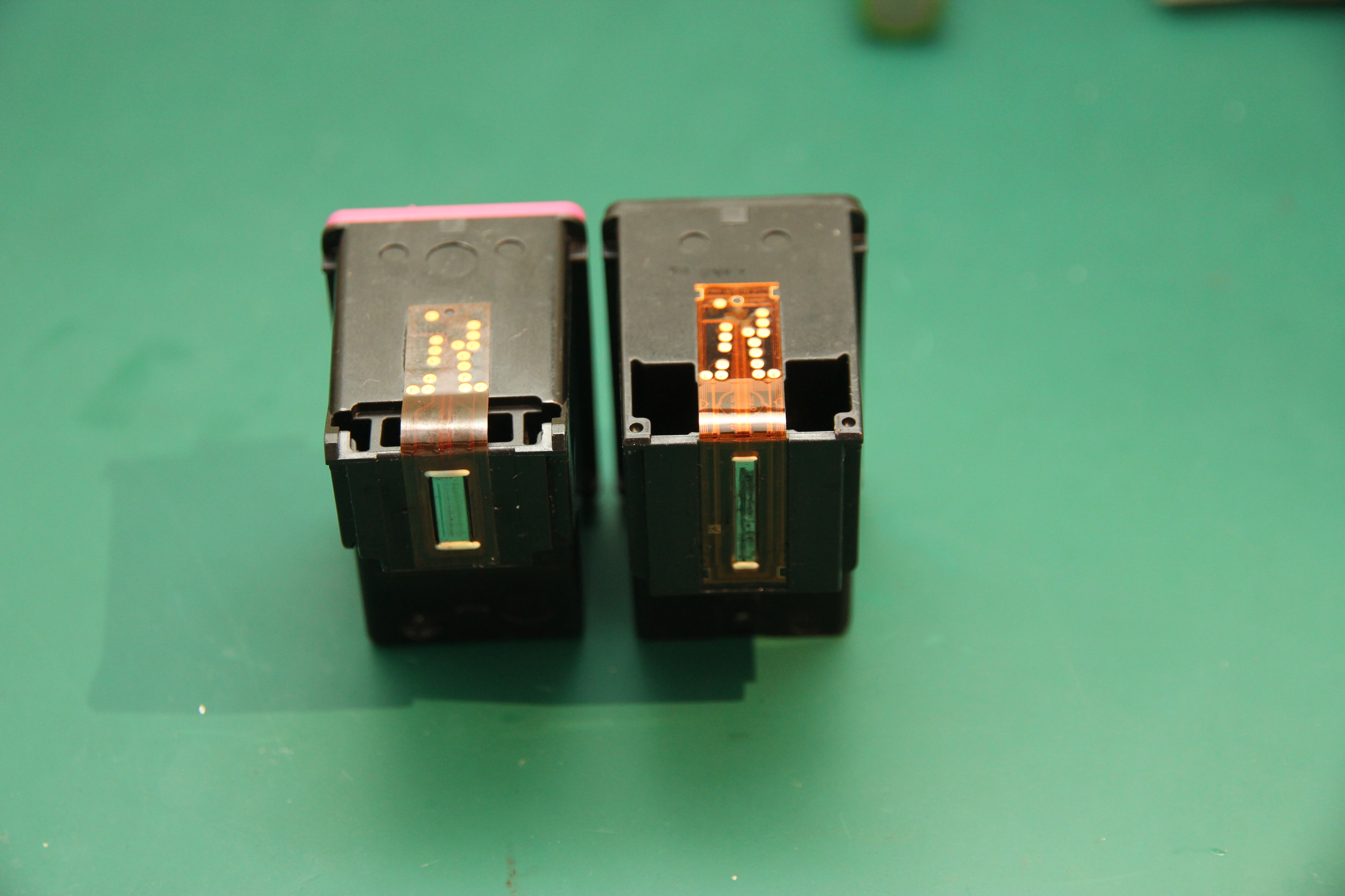
So, these are the cartridges in question. Seen from a high level, they're pretty simple things: on
the inside, they're mostly a sponge, filled with ink. Very little ink indeed in case of the 'setup cartridge'
you get with the printer, only half the cartridge is used for the sponges and the sponges themselves are also
half empty:

On the side, there are 16 contacts, running off to the bottom where the print head resides. As you may have seen in the microscope shots on the previous pages, the print head of the black cartridge has about 336 nozzles while the color cartridge has 612 of them. The nozzles are in vertical rows on the print cartridge, and each nozzle can be electrically controlled to shoot a miniscule drop of ink down towards the paper in the printer. By also moving the head vertically, the printer can print a 'band' of whatever needs to be printed; this band is about 15 mm in the case of the black cartridge and 8 mm with the color cart.
The nozzles can, obviously, be controlled with the contacts. According to the tiny writing on the print head,
the contacts carry these specific signals:

As there only are 16 contacts, there's some kind of multiplexing scheme used in order to control them all. The patent explains how this works: the nozzles are controlled in 14 different groups. These groups fire sequentially: first, group 1 gets its data and fires, then group 2 gets its data and fires, then group 3, etcetera. Each group has a maximum of 24 nozzles, and the data for it gets sent over three data lines. For a color cartridge, the data on the three lines match the colors: D1 is for yellow data, D2 for magenta and D3 controls the nozzles that squirt cyan ink.
The patent nicely explains how this works for one data line. This figure from the patent shows the signals involved:

I have no idea why HP decided to use such a convoluted scheme to clock in the data to the nozzles. I'd say something obvious like a shift register would also have worked fine here. I do know that HP uses/used their patents as a weapon against cartridge refilling companies; perhaps a simpler solution already was patented by someone else and they needed to think up this more convoluted solution to be unique.
It's not hard to recognize the signals described by the patent in the LA capture I made:

Aside from nozzle control, the cartridge also needs a signal (csync) to advance to the next nozzle group, or to reset to the first group. You can see that in the LA picture: it shows the second-to-last and last group of the 14 groups, and the csync signal has a distinguishing waveform on the last group to 'reset' the cartridge to receive the first group next. This signal can also be used to iterate over the nozzle groups in the reverse order, useful for when the print head goes both left-to-right as well as right-to-left. While the second patent does describe how this works, I opted just to hard-code the next-group and reset waveforms the csync line showed in my LA dumps.
Note that this all happens with a fair amount of speed; as an indication, the delay between two rising edges of the DCLK signal is roughly 0.4µS, and the distance between groups is about 4µS.
We now know that every bit on the three datalines of the 14 bytes contains the fire enable going to one nozzle. If this bit is 0, the associated nozzle will fire; if it's 1 the nozzle will not fire. What we do not know is the mapping between nozzles and bits. If you watched the presentation, you'll know that I managed to figure this out by printing a known pattern on a working printer, capturing the signals using my logic analyzer, then figuring out what the order of signals should be in order to decode the waveforms back into the original image. Unfortunately, the mapping of bits to nozzles seems to be somewhat regular, but not entirely logical. It seems to be mostly driven by the need to have the nozzles that fire at the same time be physically apart by a fair bit (to mitigate overheating or pulling a local vacuum in the ink tank), I figure that aside from that, ease of routing of signals in the printcart may make the mapping look somewhat confusing. In my firmware, I simply implemented this mapping as a set of lookup tables.