Electronics
Now we know how the signals work, we can control the printer cartridge from a simple microcontroller, right? Well, not immediately. The printer cartridge does not use simple 5V or 3.3V logic. Instead, the data lines are all driven by 16V or 9V lines. The power lines are also driven by 16V, and can actually pull up to an amp from the power supply, dependent on how many nozzles fire. We'll need to do some level conversion.
As level converters, I picked the MC14504. This is an older unidirectional hex level converter chip, but it can go up to 18V. While this chip works, in retrospect, I feel it may not have been the best choice: it can only output a few mA and has a fairly long propagation delay. I think it delays some of the output signals slightly depending on the cartridge and the load it puts on the outputs of the chip. I have at least one cartridge that needs some slight tweaking of the timing signals to work and I think this is the reason. Unfortunately, off-the-shelf level converters that work up to 16V aren't that common anymore, so I also can't easily substitute it for a better one. This classic chip, plus some timing tweaks where necessary, will have to do.
The power lines are a bit more complicated. Apart from these pins drawing a fair bit of current, they are also
directly connected to the nozzle resistors of the enabled nozzles: if for some reason power is applied for too
long, these tiny resistors will blow out and the nozzle is permanently disabled. Additionally, 'too long' is not
hard to reach: these nozzles should only be enabled for a few µS and powering them for even a timespan as
short as a millisecond can already vaporize them, rendering the nozzle permanently broken. In order to make
sure that wouldn't happen due to a software bug or a bad connection, I added some hardware logic to make
sure the pulse was limited to a small multiple of 10 µs.

In the first prototype, I had some level converters left and I didn't know how the software would work out,
so I decided to throw a true monostable multivibrator at the issue. Here, the two multivibrators in the
74HC123 are used to generate pulses whose width is defined by the R/C combo connected to the RCExt pin.
The resulting pulse only gets generated when there's a low-to-high input signal, so a stuck-high signal on the
input will not lead to anything more than an exactly-defined but stray pulse on the output. After this, a
channel of the MC14504 is used as a level converter to get the voltage up to +16V, and a P-channel mosfet
makes sure the needed current can be sourced.
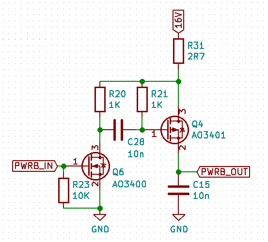
In the second PCB, I realized I could do with only two MC14504 chips if I re-designed the power pin logic not to use up two of the level shifter channels. By now, I also had a pretty good control over the pulse width from software, but still wanted to have protection from a stuck-high input pin. This is the schematic I came up with. It works like this: Normally, with PWRB_IN low, C28 is empty, as any voltage in it slowly leaks away through R20 and R21: the gate of Q4 is high and PWRB_OUT is disconnected from the 16V power rail. As soon as PWRB_IN is made high, Q6 will ground one end of C28; as the voltage over it is zero volt, initially this will also pull down the other side of it, which is connected to the gate of Q4. Pulling the gate of Q4 low will make it conduct, and this will allow current to flow from +16V into PWRB_OUT. Normally, PWRB_IN will go low again pretty quickly, raising the gate of Q4 and cutting the flow. However, while PWRB_IN is kept low, C28 is slowly charged: one side is grounded by Q6 and the other one is connected to 16V via R21 and R31. Once the capacitor has charged enough, Q4 will see a high input on its gate and will shut down the current flow into PWRB_OUT, even if PWRB_IN is still high. This mechanism guarantees PWRB_OUT can only source power for a limited amount of time.
The schematic also has a small resistor in series with the 16V power line (R31) as well as a small capacitor in parallel with the output signal (C15). These are meant to 'take the edge off' the power signal: without these, the sudden turn-on and turn-off of Q4 would induce a ton of EMC, disturbing the other signals going to the cartridge.
Apart from this logic, there's not much more needed. The level converters need the +9V and +16V, obviously. The +9V power supply needs are pretty modest: I have not seen those lines use more than a few mA in total. As it powers the nozzle resistors, the 16V supply needs to be a bit more beefy: I made sure mine could deliver at least 400mA continuously and I added in a fair bit of decoupling capacitance as well.
Finally, the all-important load of image processing and signal generation falls on the shoulders of a microcontroller. I chose the ESP32 for this, mainly because I can just take some from work, but also because it has a pretty capable I2S controller that has a really nice parallel mode tacked onto it: you can effectively just set the clock rate, point the I2S controller at a memory region, and it will clock those bytes out in parallel. This makes it ideal for generating the needed control signals; the fact that it has two 240MHz capable cores helps with the image processing as well.