Connecting it to a PC
A pulse counter like this is quite simple to control: every time a pulse is sent to its input, the number displayed by the cylinders inside mechanically is increased by one. According to the label on the side, this one needed a 24V-pulse to do its work. That could pose a problem: 24V isn't something a PC usually works with: almost all ports use 5V.
There's one exception, though: the serial port can output voltages of
-10/+10V at 20 mA. Normally, that's not enough: 10V doesn't make the counter
'click' and even if it did: it needs more than 20mA to do its job. Luckily,
I had a few tricks up my sleeve to make it work: if you set one pin on the
serial port to output -10V and another to +10V, you end up with a 20V voltage
difference, which is enough to allow the counter to do its thing. If we then
store that 20V in a capacitor and use another output pin to discharge the
contents of the capacitor on the counter, we have sidestepped the
20mA-restriction too. All in all, I arrived at the following circuit:
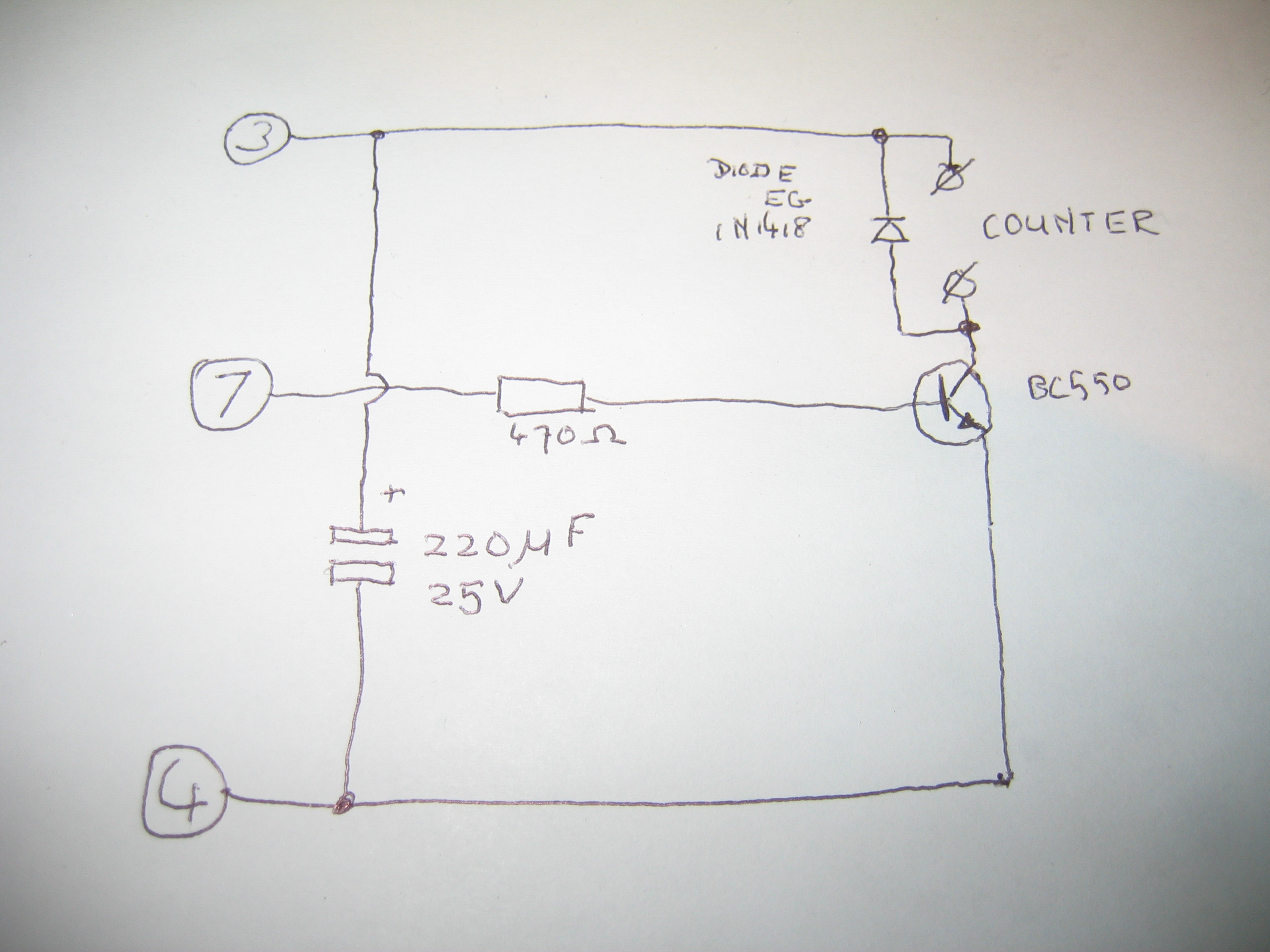
(The transistor is a standard NPN signal transistor, I used a BC550. The numbers
on the left denote DB9 serial-port pin numbers.)
The circuit does have one problem, by the way: if for some reason pin 4 of the serial port becomes positive while pin 3 is negative, the electrolytic capacitor is reverse-polarized and in theory can explode. In practice, I don't think that'll ever happen with a maximum current of 20mA, so I haven't built a protection for that. You have been warned, though.