Conclusion
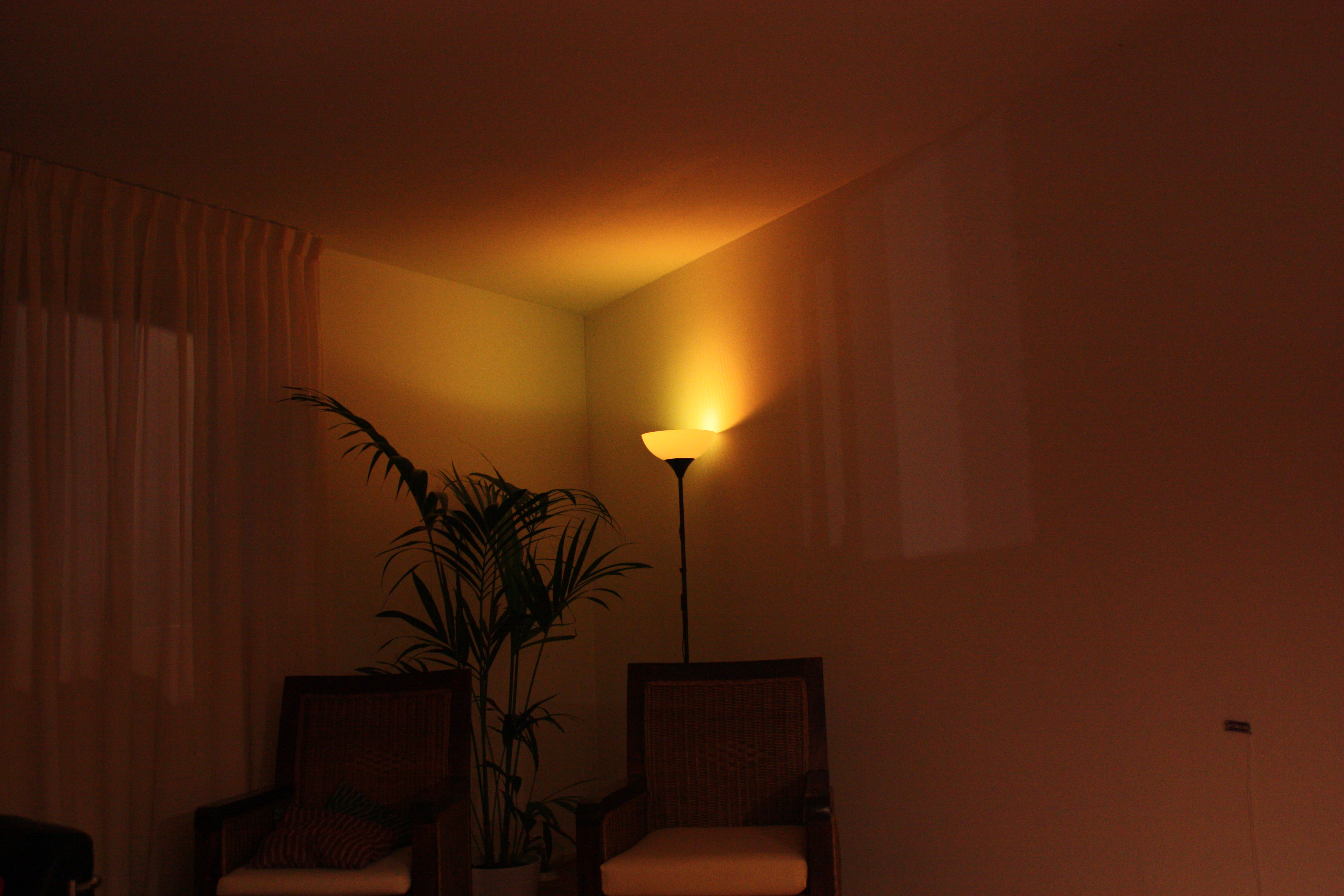
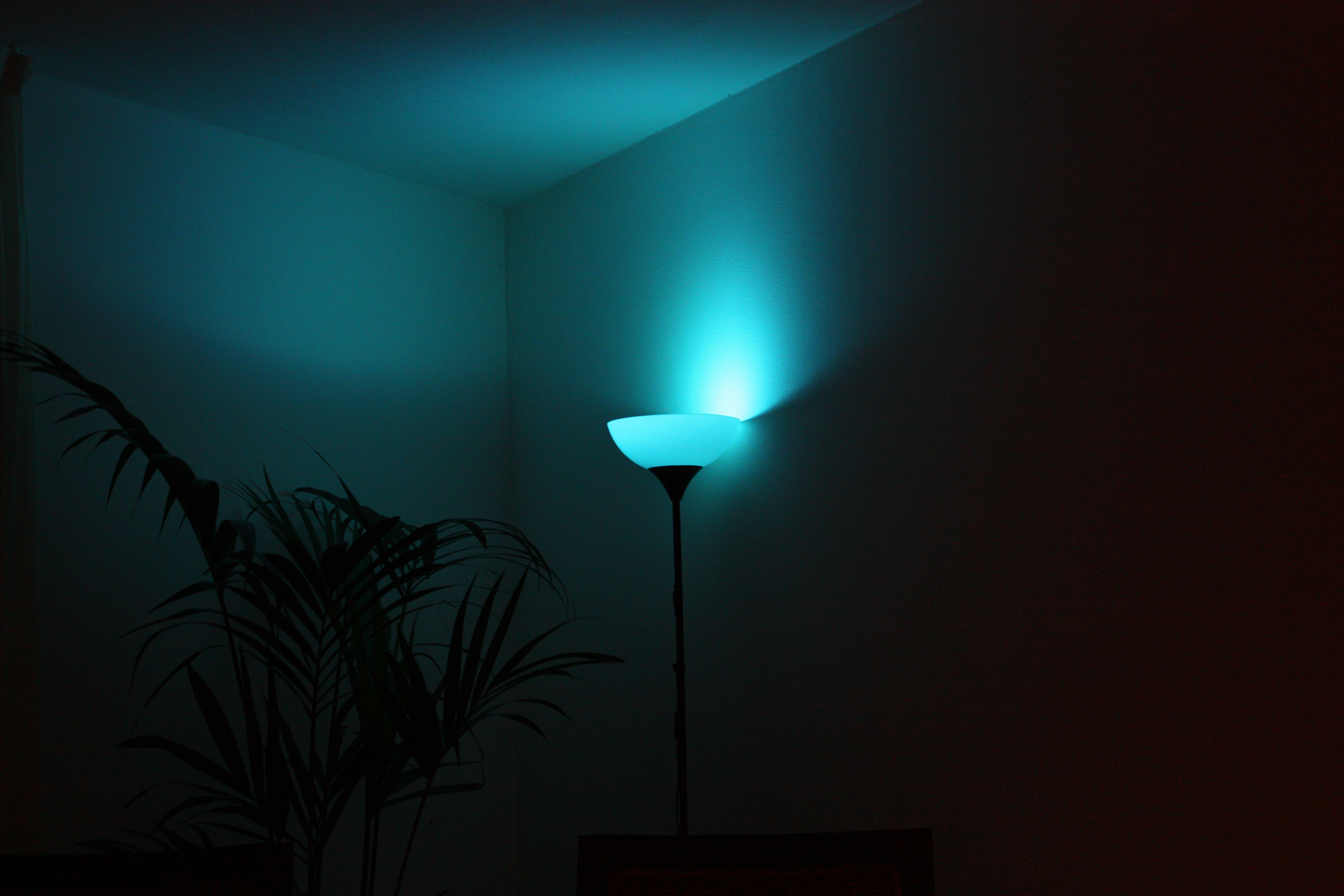
The unit works quite well as a mood light:


It's a bit too bad that after I've built the device, I found out that DealExtreme
has a RGB-ledbulb
for just a bit more than the component costs of my device. It is controlled
by IR instead of my RF-solution, but still: if I'd known the product existed
before I made this one, I would have tried hacking this first. Ah well,
we live and learn, and I've ordered one to make fitting an RGB-led into my second
bulb easier. If anything, I've gained some insights into LEDs and buck-converters
with this project, and that's worth something too.
« Prev 5
15 commentsExcellent writeup, but you can save yourself a whole lot of trouble by modifying an exsting Osram Parathom LED lamp which has all the PSU, micro (ATTiny14), RGB LEDs and LED drivers built in, plus it can sense the state of the incoming power (originally so that the mains frequency could be used as a clock to keep multiple lamps synchronised), so you could (for example) use an on/off switch to change the colour (I\'ve done this myself). One word of warning is that everything in these lamps should be considered to be at mains voltage, so no programming or debugging when it\'s plugged into the mains, unless you want to fry yourself or your equipmnent. Good Luck!
I was wondering what frequency you used for the PWM signal. It\\\'s not entirely apparent to me from your source code.
How did you determine the inductance of the coild?
ohhh, im getting in. i need the resistor to control my pwm signal, cause if i open the nmos with VGS = 5 the led would be destroyed. So in the end i can use any nmos which has high enough maximum ratings?
Hey, thanks alot for this wonderfull Project. im new at led driver so hope you can help me: Instead of 1N5619 i use 1N4007. You know another Nmos Mosfet which can be used instead of the IRLZ34? I cant find them at my dealer next street. The 0,22 poer resistors are only for meassurements? I want to build this circuit without them, because i want an automatic fading without usercontrol - so i dont need them?! Thanks alot for your help and sorry for my bad english.
it's nice, but too expansive fo use the RF modules, should use IR remote.
Great!I was wondering If I could use this rgb led to create ambient light for Tv? Best regards
slimfish you expatiate good
quick comment on your perceived nonlinearity in the LED with linear PWM increase...it is your eye that is nonlinear, but rather logarithmic in its perception of light intensity. Program the PWM values in exponentially increasing steps and you'll see an apparent linear increase.
Slimfish: That was my initial idea, and then I remembered the module was common-anode...
Hi Sprite, first of all, crongratulations for your all projects. You get creative in every project you make and that's quite difficult (At least for me :-). Maybe i'm wrong, but you could simply measure the current across each LED with only one pin (per LED). It's simple: attach resistors to VCC instead of after the LED. This way, your reference is VCC and as the ADC_REF in uC is also VCC you only have to negate ADC_RES to get the current value. I could send you a diagram if you're interested. Again, very very nice work. Toni
Apart from my eyes being broken because of the yellow on white captcha, this was a cool project... However, you mention a usb-to-433mhz project, which I can't seem to find on your page... Very interesting, details? ;) Christian...
Very nice project. I also want to build some RF controlled RGB lights. Like the current measurement in the AVR. Are you using the "klik-aan-klik-uit" protocol? Would love to see you hack the IR Conrolled (love chinese spelling) to RF controlled. If you finish both, could you do some power measurements?
Hi, i like your switching design for the current source. I've also got some heat/energy problems with a similar design using the 3W led from dx. What concerns me is the probability of damaging the led if the pwm stops/fails and the noise produced on the power lines. My opinion for the dx led: It one of the better ones! I've tried various 3W rgb leds and settled for the dx led as it gives a good mixing of the colors and is damn cheap. Greetings, Tobias
Great entry. Looking forward to the next.