Electronics
As mentioned before: every 2 RGB-strips have a shared controller consisting of
6 MOSFETs, an AVR, a 78l05 and a MAX485. There aren't too many ways to create
a working device from these components, so the schematic shouldn't come as a
total surprise.

On the left is the power supply for the AVR/MAX485: a standard 78l05 which converts the incoming 12V to 5V. Under it is the MAX485, which is hardwired to only be able to receive data from the bus. The output-pin goes to the RxD-pin of an ATTiny2313, which processes the data. Not in the schematic (I kinda forgot to draw it...) is the crystal, hooked up to the AVR in the usual way. The ATTiny2313 is clocked at 20MHz: that is the maximum rate it can run on and that way I can increase the PWM frequency nicely. The AVR directly drives the 6 low-voltage MOSFETs which switch the cathodes of the LED-strips, and that's basically all there's to it.
I tried to get as little flickering in the LEDs as possible, so for speed, the programming of the AVR is written in assembly. The PWM-routines are ran from a timer-interrupt, which is tweaked to trigger about every 50th clock cycle. That way, I get a 6-channel, 8-bit PWM-routine which runs at 1.5KHz. Apart from that, there's a small routine which receives serial bytes from the MAX485, and dependant on the address set by the address lines, uses some of it as the PWM-values.
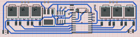
Because I had to build 7 of the controller boards, I decided on etching a PCB for it. That way, I could SMD-components for everything I needed, which makes the PCB nice and compact and much quicker to solder. (If you know how, even a 20-pin SMD-IC is quicker to solder than it's DIP counterpart.) The PCB-design is quite specifically made for hand-soldering btw; for example, you're supposed to wire the LED-strips immediately to the tabs of the MOSFETs. This does, however, make the design much simpeler, making it into a single-sided design with no drill-holes needed and nice, big traces.